ACP utilizes Revit massing elements to identify portions of a building which deviate from the standard X-Y-Z orientation. This approach enables ACP to detect regions where conduit routing follows non-standard directions, ensuring precise path generation. To ensure proper routing, all Electrical Model elements within an Off-Axis mass must share the same orientation. This includes Electrical Equipment, Electrical Fixtures, Guidance Boxes, Scoping elements, and any existing conduits, conduit runs, and fittings.
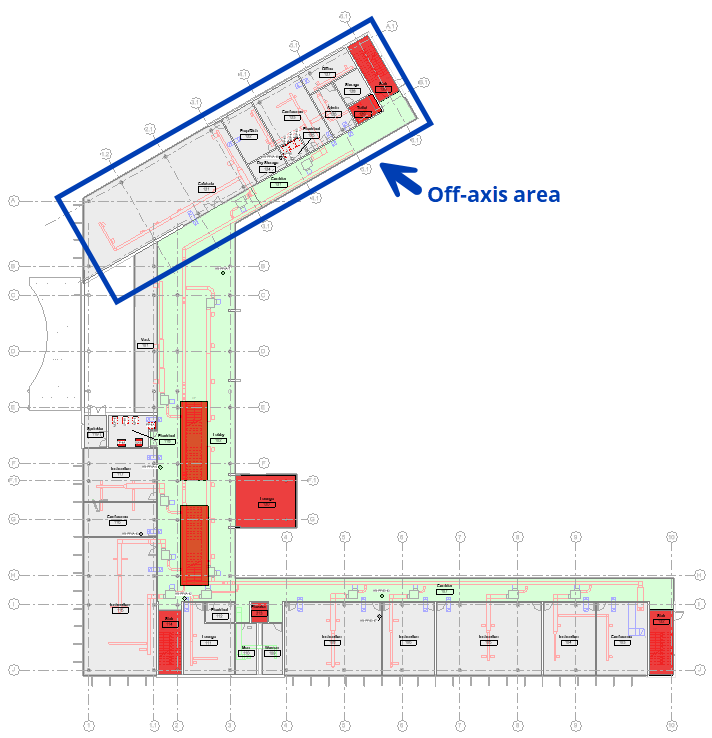 Create the off-axis mass
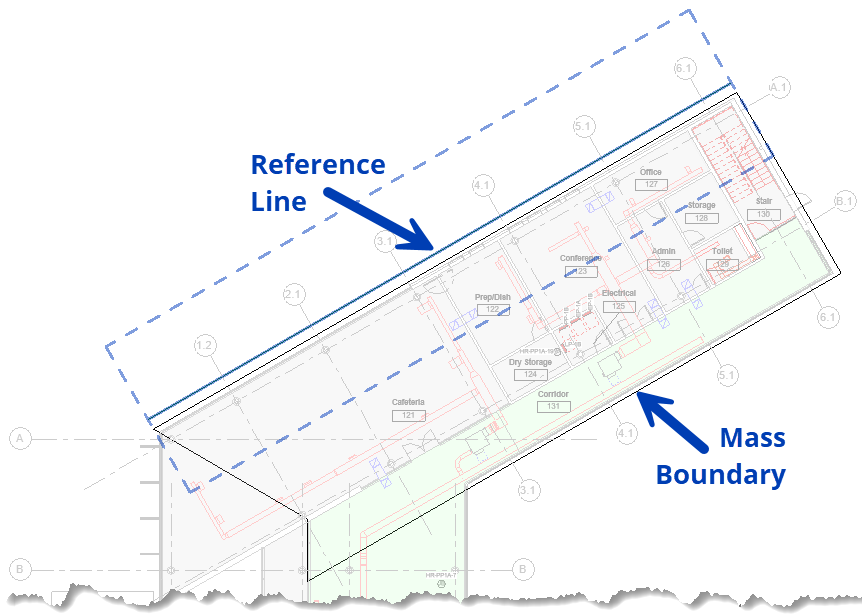
Create the mass boundary
In Revit navigate to the Massing & Site tab, and select In-Place Mass
.png) from the Conceptual Mass panel.
from the Conceptual Mass panel.Name the mass (e.g., "Off-Axis Area" or “Area B”, etc.) for easy identification.
In any floor plan view, use the Draw tools to create mass model lines around the area’s perimeter.
Because these lines become the boundary where the routing axis changes, it’s crucial to consider the following:
Building direction changes: Locate points where shifts occur, such as at intersections or turns, and determine where along that shift the conduits should change direction.
Building features: It may be helpful to use structural elements, walls, corners, and partitions as natural markers for pivot points.
Overlapping masses: Touching masses are acceptable, but overlaps may cause routing errors.
PRO TIPS:
Rather than manually creating a boundary, use the Pick Lines
feature and select the exterior walls.
When outlining the boundary around the exterior walls, it may be helpful to offset the line by a foot or two, to ensure the targeted area is completely encompassed.
The Trim/Extend Corner
tool helps to create clean, connected corners in your outline.
 Create the 3D form
Select the completed boundary and click Create Form
.png) to extrude the mass.
to extrude the mass.In a 3D or Section View, adjust the height of the newly created form using pull points to encompass all building levels and elements affected by the off-axis configuration.
Consider Multi-Level Changes: Ensure the mass accommodates shifts across multiple building levels.
Place an Axis Line
Draw a straight Model Line
.png) in the direction you wish to set for the X or Y orientation within the mass volume.
in the direction you wish to set for the X or Y orientation within the mass volume. This will typically align with a grid or a wall within the off-axis area.
ABOUT THE REFERENCE LINE:
Defines the new x-y-z axis for the area of the building encompassed by the Off-Axis mass, so the direction it runs is crucial!
Is the element that tells ACP that this mass should be used as an Off-Axis region. If there’s no reference line, the Off-Axis mass will be ignored.
Must only exist once within the Off-Axis mass. If more than one line exists within the Off-Axis Mass, ACP will not be able to correctly read it.
Does not have to be within the boundary of the Off-Axis volume.
It may be helpful to offset the reference line outside the mass for better visibility during configuration.
Finish the mass
Select Finish Mass
.png) to complete the mass and exit the In-Place Editor.
to complete the mass and exit the In-Place Editor.
 Align Electrical Model elements
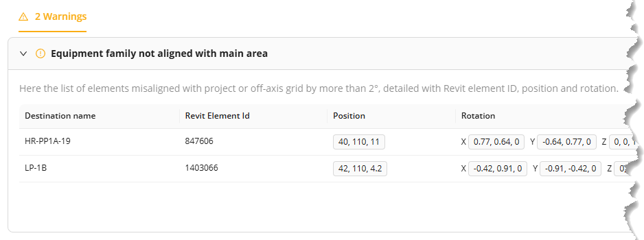
In order for conduit to properly connect to Electrical Equipment and Electrical Fixtures within the model, the element must be aligned with the model’s axis. This includes orienting it to the axis specified within any off-axis mass.
If any Electrical Model element is rotated more than 2° off the specified axis (Either your default x-y-z axes or line defining the orientation inside of the off-axis mass) , the warning Equipment family not aligned with main area will appear after the electrical model is imported into the study.
Families in Revit are built with specific hosting or attachment methods (IE: Wall hosted, Floor hosted, Face hosted, etc).
There are many ways to realign or reorient elements within a Revit project, many of which may be dependent on the hosting method (typically Non-hosted or Face hosted) of the family being used.
Here are a few suggested methods:Non-Hosted Families
Align tool

Locate the Axis Line within the Mass.
If there are walls or other references that are the same orientation as the Axis Line, those may also be used.
Select the Align tool in the Modify tab.
Select the reference (Either the Axis Line, or the reference with the same orientation).
Select the appropriate edge of the electrical element.
Use the Move command
to adjust the final location of the electrical element if needed.
Rotate command

Locate the Axis Line within the Mass
If there are walls or other references that are the same orientation as the Axis Line, those may also be used.
Ensure the appropriate edge of the element is in some way intersecting with the reference (Either the Axis Line, or the reference with the same orientation)
Select the electrical element in the model.
This will automatically redirect you to the Modify tab
Select the Rotate command in the Modify tab.
Select a new Center of Rotation
Click on the dot, Press spacebar, or click the Place button
in the options bar, to pick the center of rotation up
Place the center of rotation where the electrical element intersects with the reference.
Select a point on the appropriate edge of the element to start rotation.
Click a point on the intersecting edge of the reference to complete rotation.
Use the Move command
NOTE: An angle may also be entered into the rotate command, instead of rotating it to a reference. This may be helpful when a reference is difficult to find. Either use the measurements listed in the error, or use an angle dimension to determine the needed angle.
Face-Hosted Families
Pick New Work Plane

Face-hosted elements depend entirely on the orientation of their host (the element they attach to). Because they can be hosted on any face of any model object, an element attached to a host with the wrong orientation will also be misaligned. The only way to correct this is to assign the element to a new host with the correct orientation.
Locate the Axis Line within the Mass
Check the wall orientation:
Determine if the wall the electrical element should be hosted to matches the orientation of the Axis Line.
If the wall orientation does not match:
Option 1: Locate another host for the electrical element.
Option 2: Create a Reference Plane
in the correct orientation, and use it as a host surface.
Select the electrical element.
This will automatically redirect you to the Modify tab, in the Placement panel.
Select the Pick New Work Plane button, to detach the element up from it’s current host.
Ensure the option for Vertical Face
is selected as the placement option.
Place the element on the new host (either the wall face, or the Reference Plane).
NOTE: Reference Planes can serve as host surfaces for face-hosted elements. In Revit, they display as dashed lines that appear to begin and end, but actually extend infinitely within their defined plane. When using Reference Planes as hosts, it is best practice to name and pin them to ensure they are easy to locate, reuse, and protect from accidental movement.