The Trim Conduit tool eliminates many of the manual steps required to reconnect segments of conduit after modifications have been made to a run.
As coordination progresses, conduit solutions will often need to be adjusted. Typically the easiest way to do this is to split a conduit at the desired location, or delete existing bends, in order to adjust the segments. Once modified, those segments then need to be reconnected.
In native Revit, this is a multi-step process which involves duplicating and rotating conduit, then using the Trim/Extend corner tool to join them. The Trim Conduit tool handles this in a single action for all segments within a rack, inserting the appropriate fitting (a bend, offset, or kick) based on the position of the conduits and your preferences.
The Trim Conduit tool is Selection Specific so the steps below reference the Modify tab workflow.
Join Conduits
Whenever a run of conduit is broken, such as when a segment is split within the run, Revit will consider each side of the split or break as a separate run, which can impact the count, length, and data within the model. For conduit segments which are at the same elevation, and running along the same path (lateral position), the run may be reconnected simply by dragging the conduit connector from one segment to meet up with the connector in the other.
 The Trim Conduit tool will join any two selected conduit segments at the same elevation and running along the same path (lateral position)
Select the segments on each side of the split.
This will navigate you to the Modify Conduits tab.
From the Modify Conduits tab, click the Trim Conduit tool
The two segments become joined together into a single segment and the run can continue.
If the two segments have different ACP parameter values and/or size, the tool will use the properties from the segment to the right.
Conduit split across an entire rack may be joined simultaneously.
Select the segments on each side of the split.
This will navigate you to the Modify Conduits tab.
From the Modify Conduits tab, click the Trim Conduit tool
The segments on each side of the split become joined together into a single segment, and the run can continue.
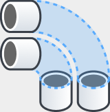
If two segments have matching ACP parameter values but are in different positions within the rack on each side of the split, those segments will be matched to each other rather than to the segments running along the same path. Because they are not aligned, the tool will activate the Offset in order to connect them rather than a simple join.
Create Simple Bends
When conduit segments at the same elevation need to be connected with a change in direction, or when a run or rack changes direction to run vertically, those bends are considered simple, because they only require a bend at whatever angle the adjacent segments meet. The Trim Conduit tool may be used to connect two adjacent conduits into a single run, or multiple adjacent segments from an entire rack.
 The Trim Conduit tool will connect any two selected conduit segments at the same elevation regardless of size, and angle.
Select the two segments which need a bend
From the Modify Conduits tab, click the Trim Conduit tool
A simple bend is placed at the correct angle to connect the two segments.
If the two segments differ in size, Revit may place additional transition fittings automatically.
, with one key difference:
When one or both segments contain ACP parameter data, those properties are automatically transferred to the new bend element.
If the two segments have different ACP parameter values, the tool will use the properties from one of the segments.
When multiple conduit segments are selected from a rack, the Trim Conduit tool connects each set of conduits with a simple bend at the corner angle, using the ACP_E_Conduit_Run_ID parameter to match segments when values are present.
Select multiple adjacent segments from the rack which need to be connected.
From the Modify Conduits tab, click the Trim Conduit tool
. If the segments contain matching values for the ACP_E_Conduit_Run_ID parameter, a simple bend is placed at the corner angle of each matching set, and all ACP properties will be copied to the new bends.
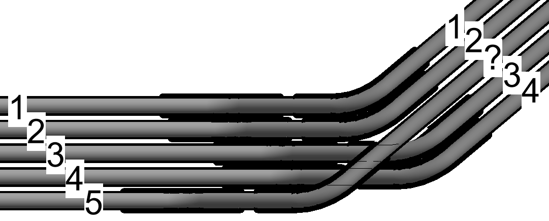
If no matching ACP_E_Conduit_Run_ID values are found in the adjacent rack, a simple bend is placed starting at the inner corner and moving outward to connect adjacent conduits at the correct angle.
If the segments containing the matching values for the ACP_E_Conduit_Run_ID parameter, have been moved around in one of the adjacent racks (and not the other), the conduit bends may end up crossing other bends, causing self-collision.
Create Multi Bends
When conduit segments need to connect across a lateral shift, a vertical shift, or a change in elevation, an angled segment and matching bends must be placed between them. The Offset function of the Trim Conduit tool handles this automatically, inserting the diagonal segment and all required bends in a single action. When the run also includes a change in direction, such as turning a corner, the Offset option will also place the additional simple bend required to handle it.
In cases where reducing the total number of bends is a priority, a Kick may be used instead. Rather than adding a simple bend, the Kick rotates that bend into the vertical plane, consolidating the corner change into two bends rather than three. This minimizes pull box requirements and allows runs to fit into tighter spaces. When a vertical shift is accompanied by a lateral shift, a Kick is required.
Create Offsets
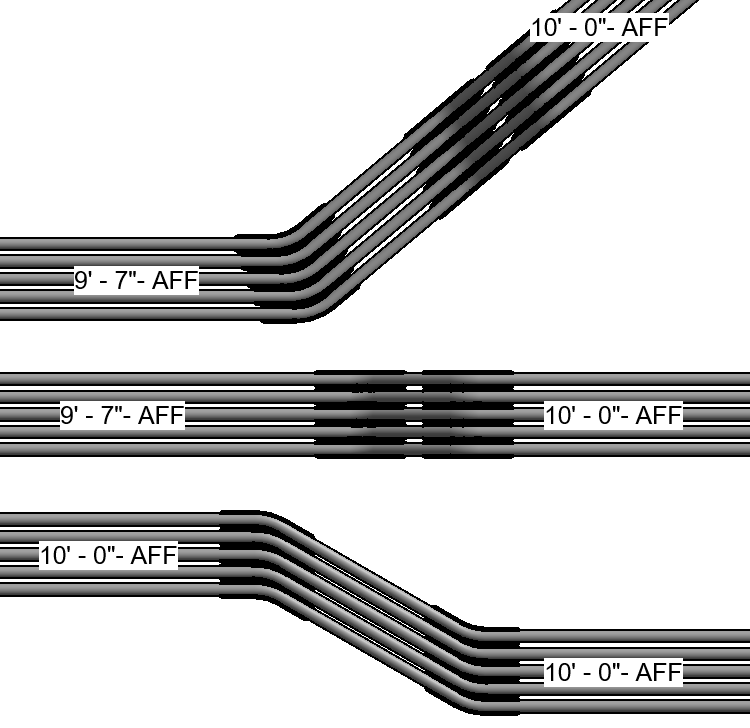 Use the Offset function to connect conduit segments across a lateral shift or a change in elevation. When a change in elevation is accompanied by a change in direction, the Offset function will also place the required simple bend to account for both.
Select two or more segments to be joined.
This will navigate you to the Modify Conduits tab.
From the Modify Conduits tab, click the Trim Conduit tool
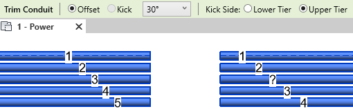
This will activate the tool and display a secondary Trim Conduit options bar.
Set the radio button to
 Offset in the options bar.
 The Kick option will be grayed out unless the conduit run includes a change in direction.
Specify the other properties.
 Bend angle - The angle of the two Offset bends.
 The tool will default to the preferred 30° angle
Use the drop-down list to change to a different preset angle. 5°, 10°, 11.25°, 15°, 22.5°, 45°, 60°, 90°

Kick Side - The side of the offset where the rack will change elevation.
Lower Segment - The segment which is either lowest in elevation.
Upper Segment - The segment which is either highest in elevation.

Click Confirm or Press Enter to complete the command and create the offset.
Expand to see how conduit segments are paired for Offsets
For Lateral offsets, the two conduits which are offset lowest will connect first, and then the next two lowest, until all are connected.
For Elevation Change offsets, conduits which are aligned will be joined, regardless of size.
For Elevation and Direction change offsets, Conduits will be joined similar to a simple bend, starting at the inner corner and moving outward to connect adjacent conduits at the correct angle.
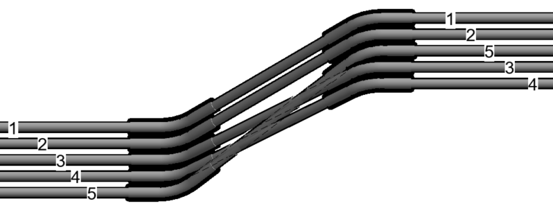
When segments contain matching values for the ACP_E_Conduit_Run_ID parameter, those two segments will be joined together, regardless of their placement or alignment in the rack.
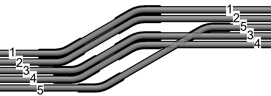 Please Note: If segments with matching values are not in the correct physical positions relative to each other, the parameter match will override the default positional behavior, and conduits may shift diagonally or cross incorrectly.
If the two segments have different ACP parameter values, but not a simple bend, the tool will use the properties from one of the segments.
If the offset also contains a simple bend (due to a change in direction), the simple bend is placed opposite the Kick Side, and will inherit the properties of the segment nearest it.
Use the Push Properties tool to align the properties through the entire run and ensure consistency.
Create Kicks
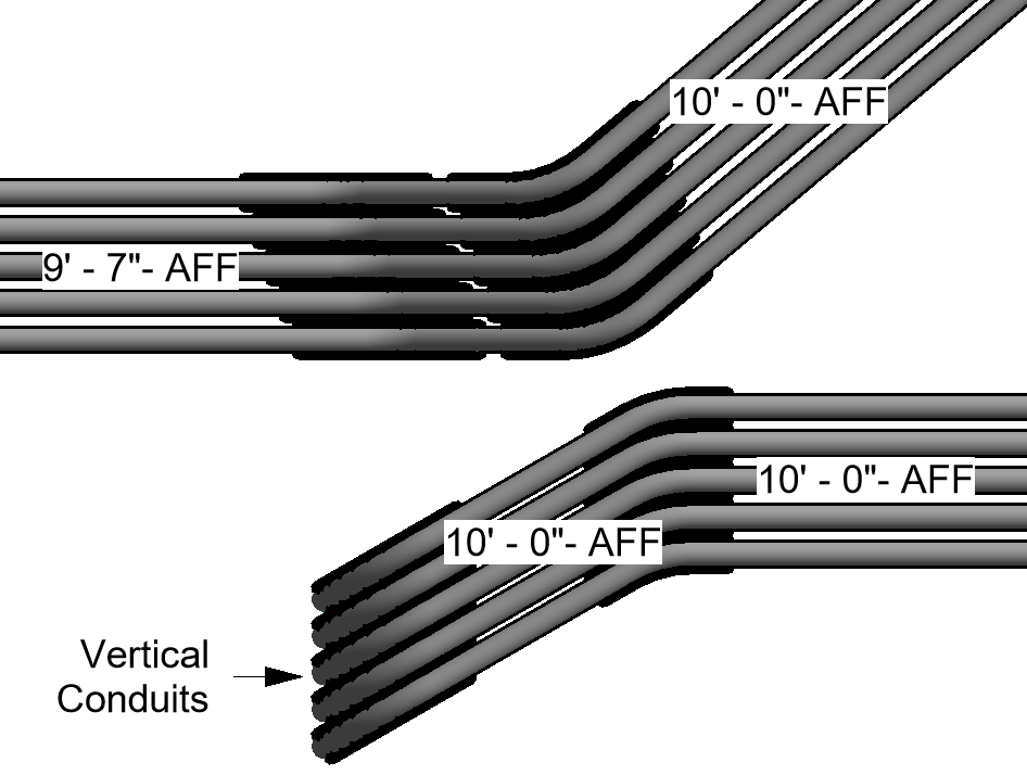 Use the Kick function to connect conduit segments when a change in elevation is accompanied by a change in direction, or when a vertical shift is accompanied by a lateral shift, to reduce the number of bends required and allow runs to fit into tighter spaces.
Select two or more segments to be joined.
This will navigate you to the Modify Conduits tab.
From the Modify Conduits tab, click the Trim Conduit tool
This will activate the tool and display a secondary Trim Conduit options bar.
Set the radio button to
 Kick in the options bar.
 Specify the other properties.
 Bend angle - The angle of the single kicked bend.
The tool will default to the preferred 30° angle
Use the drop-down list to change to a different preset angle. 5°, 10°, 11.25°,15°, 22.5°, 45°, 60°, 90°
 Kick Side - The side of the Kick where the rack will change elevation.
Lower Segment- The segment which is either lowest in elevation, or closest to the bottom of the plan view for lateral offsets.
Upper Segment - The segment which is either highest in elevation, or closest to the top of the plan view for lateral offsets.

Click Confirm or Press Enter to complete the command and create the kick.
Expand to see how conduit segments are paired for Kicks
Conduits will be joined by the Kick the same way as a simple bend, starting at the inner corner and moving outward to connect adjacent conduits at the correct angle.
When segments contain matching values for the ACP_E_Conduit_Run_ID parameter, those two segments will be joined together, regardless of their placement or alignment in the rack.
 Please Note: If segments with matching values are not in the correct physical positions relative to each other, the parameter match will override the default positional behavior, and conduits may shift diagonally or cross incorrectly.
The Trim Conduit tool will push the properties from the ACP parameters through the associated bends and angled segment.
If two segments are joined and have different ACP parameter values, rolled bend from the kick is placed opposite the Kick Side, and will inherit the properties of the segment opposite.
Use the Push Properties tool to align the properties through the entire run and ensure consistency.
Create Rolling Offsets
When a Lateral Offset is accompanied by an Elevation change, the two equal bends of the Lateral Offset should be rolled (similarly to how a single bend in a Kick rolls), to allow for the bi-directional change to occur.
Select the two segments which need a bend
From the Modify Conduits tab, click the Trim Conduit tool
A bend is placed at the end of the two adjacent segments, and are rolled to an angle required to be connected by a diagonal segment.
The angle of the bends being rolled will start at the inner ends of each segment selected, and be determined by the roll itself. This means the bend angle will not be standard, and so the process will feel very much like creating simple bends.
Expand to see how conduit segments are paired for Rolling Offsets
When a single run is selected, and one or both segments contain ACP parameter data, those properties are automatically transferred to the new bend element.
If the two segments have different ACP parameter values, the tool will use the properties from one of the segments.
When Multiple runs are selected, and the segments contain matching values for the ACP_E_Conduit_Run_ID, those segments will be connected.
If the segments containing matching values for the ACP_E_Conduit_Run_ID parameter, have been moved around in one of the adjacent racks (and not the other), the conduit bends may end up crossing other bends, causing self-collision.