Design rules in ACP enable users to define preferences for conduit routing and support for each Study. Each Design Rule type has a default design rule created.
PLEASE NOTE: A design rule is only applied when the checkbox next to it is selected
.
Below are step-by-step instructions for configuring each rule, along with recommended settings.
Create a new design rule
Design Rules define the settings of design rule types for different Scopes within the site. Multiple design rules may be created for a single design rule type.
Follow the steps below to create additional design rules.
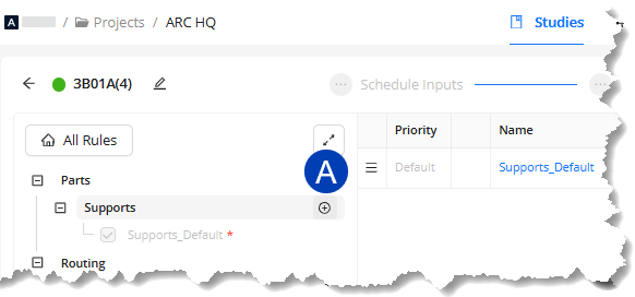
.png) In your ACP study, navigate to the Design Rules sub-tab on the Studies tab.
In your ACP study, navigate to the Design Rules sub-tab on the Studies tab.In the Design Rule panel, select the Create Rule button
.png) next to the desired rule type.
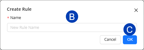
next to the desired rule type. Enter the
 Name for the new design rule in the Create Rule window.
Click
 OK to create the rule or Cancel to exit the process.
The new design rule appears in the list.
The design rule settings view opens by default so you can configure it.
Assign Supports
The design rules for the Supports type define which support types can be used to support conduits in the Solution.
Change default Support Spec
Supports are an essential part of the ACP conduit routing process, so a default rule is always enabled for the Entire Site. It cannot be disabled or deleted, but you can change the Support Spec used for its Scope.
Follow the steps below to change the Support Spec used for the default Supports design rule.
.png)
Under the Supports design rule type, select the
 Supports_Default design rule.
 Its settings will be displayed on the Design Rule viewer on the right.
Click the
 Support spec dropdown.
 Expand
 the folders as necessary to access the preferred support spec.
Select one from the
 options.
 Refer to Working in the Specifications tab to know more about support specifications.
All changes are saved automatically.
Add a Supports design rule
 To add more design rules for the Supports design rule type, follow the steps below.
In the Design Rule panel, click the
 Create Rule button for the Supports rule type.
In the Create Rule window, enter a
 Name for the design rule.
 Click
 OK to create the design rule.
Or Cancel to stop the process.
The created design rule will appear on the list and its settings will be displayed on the Design Rule viewer on the right.
 It will be appended with the priority level (P1, P2, P3…) which decides the precedence of the rules if the scopes coincide.
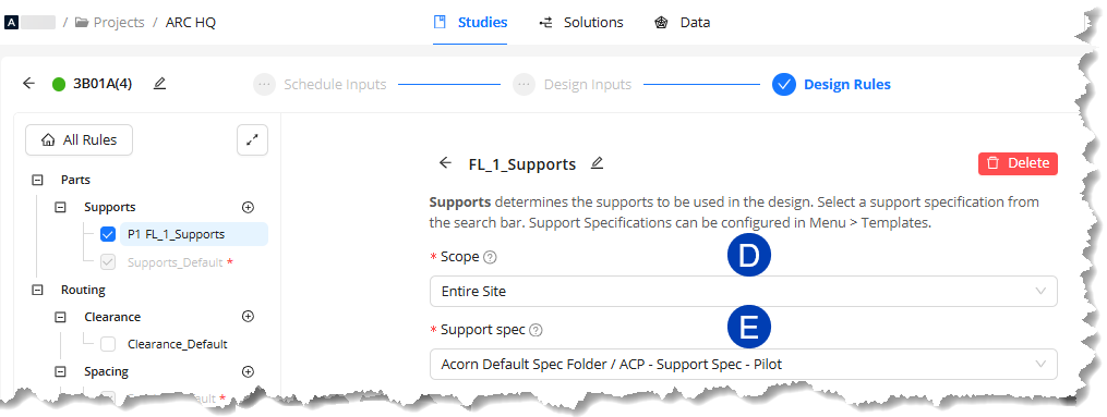
Set a
 Scope for the design rule by clicking the dropdown and selecting from the options.
Expand
the options as necessary.
Select a
 Support spec by clicking the dropdown and selecting from the options.
All changes are automatically saved.
Repeat the steps above to create as many Support design rules as needed.
Configure Clearance
Sets minimum spacing between conduits and surrounding elements (e.g., walls, doors, railings) as an additional buffer.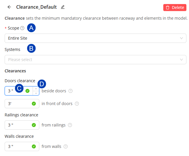
In the Design Rule panel, select or create a Clearance design rule.
Set a
 Scope by clicking the dropdown and selecting from the options.
Select
 Systems by clicking the dropdown and selecting from the options.
 This limits clearance design rule to specific conduit systems (e.g., fire alarm, power, data) instead of applying one value to all conduits, which is the default behavior.
System types are derived from the Conduit Schedule.
Set Clearances by entering the preferred value on the
 textbox or using the
  up and down arrows to adjust it.
beside doors
In front of doors
from railings
from walls
All changes are automatically saved.
PRO TIPS:
Leave the Clearance rule disabled during initial studies for a project to prevent over-constraining the model.
Any Clearance value can be set to 0" to minimize routing failures.
When clearances are required, specify values for only one or two settings at a time and adjust values incrementally as needed.
Clearances should be limited to specific requirements and minimized whenever possible.
If too many clearances are added to the design rule, conduit runs may be blocked from successful routing.
Configure Spacing
Defines minimum distances between conduits inside the racks. 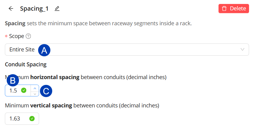
In the Design Rule panel, select or create a Spacing rule.
Set a
Scope by clicking the dropdown and selecting from the options.Set Conduit Spacing by entering the preferred value in the
 textbox or using the
  up and down arrows to adjust it.
Horizontal spacing - Consider sizes of the Unistrut clips being used
Vertical spacing - Consider the space needed for the desired support configuration.
All changes are automatically saved.
PRO TIPS:
Avoid excessive spacing, which reduces available rack capacity.
Reduce spacing in congested areas where possible to improve overall conduit routability.
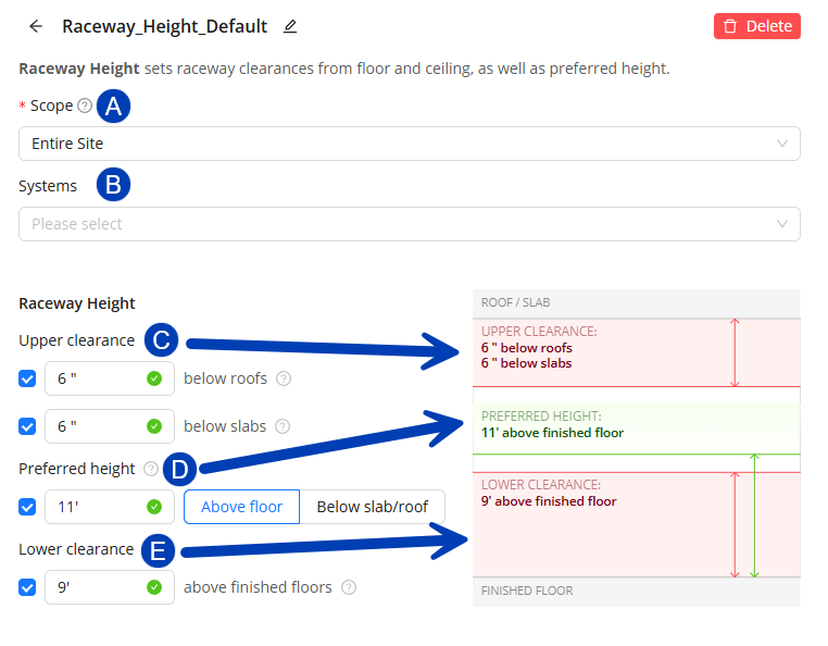
Configure Raceway Height
Ensures ACP routes all horizontal conduits within the desired elevation range, while accounting for required clearances from floor structures and the roof.
In the Design Rule panel, select or create a Raceway Height design rule.
In the default Raceway Height design rule, all settings are disabled
 , except for Lower Clearance which is enabled
 .png) .
.Additional Raceway Height design rule (applied to scopes), have all settings enabled
by default.
Set a
Scope by clicking the dropdown and selecting from the options.Select
Systems by clicking the dropdown and selecting from the options.This limits clearance design rules to specific Raceway systems (e.g., fire alarm, power, data) instead of applying one value to all conduits, which is the default behavior.
System types are derived from the Conduit Schedule.
Configure the
 Upper Clearance.
Defines the minimum spacing between the raceway and overhead structures (roofs and slabs).
The Upper clearance below roofs and below slabs are configured separately.
Click the corresponding checkbox to enable
/disable  either setting.
The Upper clearance creates a top no-fly zone which prevents both horizontal and vertical conduit routing within.
Clash-Free Boxes typically allow vertical routing across adjacent levels by allowing conduit to penetrate through obstructions above and below the element. However, because Upper clearances override Clash-Free Boxes, vertical routing across adjacent levels is blocked where Upper clearance is set.
May Route Boxes which extend below the Upper Clearance must be manually placed where conduit should penetrate the Upper clearance to allow routing between adjacent levels.
Configure the
 Preferred Height.
The target height for the conduit to route.
ACP may still route the conduit higher or lower depending on available space, supportability, obstructions, and other factors, but will try to remain as close to the specified height as possible.
Select the reference for the Preferred height as either Above floor or Below slab/roof.
Click the checkbox to enable
/disable the Preferred height setting.
Configure the
 Lower Clearance
Minimum spacing between the raceway and floor structures below to create the bottom zone where most horizontal conduit may not run but vertical conduits may enter.
Exception - ACP is able to route short segments of conduit horizontally below the Lower Clearance up to 1’-6” in two instances:
When routing around structure to get to a Source or Destination below the Lower Clearance.
When connecting two Side-to-Side panels which are within 2’-6” of each other.
Click the checkbox to enable
/disable the Lower clearance setting.
All changes are automatically saved. The diagram on the right also updates as you make your changes to give you a visual of the clearances and preferred raceway height.
Raceway clearances are determined from the Roof and Floor structures within the Revit models and are not associated with Floor Levels in the project. Check for additional floor structures which may exist outside of the typical floor level.
PRO TIPS:
Different raceway heights may be assigned to various scopes throughout the building
Horizontal conduit may not route below the Lower Clearance of the raceways except:
When routing around structure to get to a Source or Destination below the Lower Clearance.
ACP is able to create a horizontal segment up to 1’-6” from the Electrical Element to connect to the rest of the conduit.
When connecting two Side-to-Side panels which are within 2’-6” of each other.
If conduits must run great than 1’-6” horizontally to reach it’s source or destination a specific area, a separate Raceway Height design rule with the appropriate Lower Clearance must be created with a Scope assigned to that area.
Configure Routing Through Walls
Allows conduits to penetrate perpendicularly through walls within a scoped area.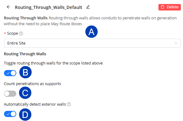
In the Design Rule panel, select or create a Routing Through Walls design rule.
Set a
Scope by clicking the dropdown and selecting from the options.Toggle
 Routing Through Walls ON
  or OFF
  .
. ON enables conduits to be routed through walls within the Scope.
OFF prevents conduits from penetrating walls within the Scope.
Toggle
 Count penetrations as supports ON if conduit penetrations need to be counted as support.
Toggle
 Automatically detect exterior walls ON to avoid routing through exterior walls at all times, even when the Route Through Walls design rule is used.
Detection of exterior walls Relies on the Function parameter within the Wall Type in Revit to distinguish between interior and exterior walls.
All changes are automatically saved.
If the Function parameter in a Wall Type is set incorrectly (for example, interior walls marked as exterior), ACP cannot properly identify exterior walls. This can block valid conduit routes, as ACP prevents penetrations through walls it sees as exterior. Conversely, if exterior walls are marked as interior, ACP may allow unintended penetrations and cause incorrect routing.There are a few workarounds which give ACP more flexibility in how it detects and penetrates walls in projects where wall functions are misassigned:
When the Function parameter of only a few interior walls are set to exterior within the project.
Toggle ON
Use may route boxes to manually create specific wall penetrations in problematic areas.
When the Function parameter of many or all interior walls are set to exterior within the project.
Create a scope box a couple of feet within the building’s perimeter to limit the scope of where the Route Through Walls setting is applied.
Assign that scope box as the scope for the design rule.
Toggle OFF
If multiple scope boxes are required to cover the building footprint, create additional scope boxes and design rules as needed.
Naming scope boxes will make them easier to identify when assigning to design rules.
If possible, correct the function parameter for the wall type within the Revit link to ensure correct behavior.
Configure Routing Through Ceilings
Allows conduits to penetrate ceilings perpendicularly within a scoped area. 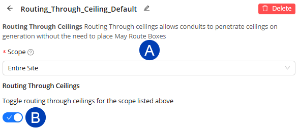
In the Design Rule panel, select or create a Routing Through Ceilings design rule.
Set a
Scope by clicking the dropdown and selecting from the options.Toggle
 Routing Through Ceilings ON or OFF .
 ON enables conduits to be routed through ceilings within the Scope.
OFF prevents conduits from penetrating ceilings within the Scope.
All changes are automatically saved.
Enable routing through ceilings when conduits need to penetrate ceilings.
For example:
When ceilings are modeled within electrical rooms.
This sometimes happens when architects want to host a light fixture, even if they don’t intend for the ceiling to be constructed.
When panels are located in rooms other than the electrical rooms where ceilings may be present.
Assign design rules to a scope in order to selectively enable routing through ceilings to specific areas within the overall site.