Grid Resolution defines how finely ACP evaluates available space versus occupied space. Smaller grids capture tighter gaps around obstructions, enabling more precise routing. Larger grids evaluate space more coarsely, which speeds up processing but may block viable paths by marking broader regions as occupied.
You can set the grid resolution when providing model inputs during study creation. The grid scale ranges from 12" to 2", with values 12", 6”, 4”, 3", and 2", moving from coarse to fine resolution. This range provides flexibility for different project and spatial requirements. By adjusting the grid size, users can balance routing precision and processing time: a finer grid offers more detailed routing in congested areas, while a coarser grid speeds up analysis but may reduce available routing paths.
This guide explains in detail how ACP grids work, and how to best leverage them in various scenarios.
Grid Resolution and routing precision
Grid Resolution in ACP controls how the project space is divided into cubes for obstruction analysis and routing optimization. This virtual 3D grid overlays the model, with each cube independently checked for obstructions. If any part of a cube intersects with an obstruction, the entire cube is marked as unavailable for routing. Similarly, the entire cube will be evaluated based on any Guidance Box that intersects with it.
Refer to the Using the Routing Tools article to learn more about Guidance Boxes.
The diagrams below illustrate how grid resolution impacts the balance between available and occupied space, highlighting the effect of different grid resolution sizes on routing precision.
.png)
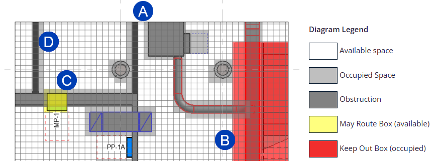
.png) A 4” grid resolution resolution creates available space for potential routing between the wall and equipment obstructions.
A 4” grid resolution resolution creates available space for potential routing between the wall and equipment obstructions. .png) The impact of the obstruction created by the Keep Out Box is kept relatively to a minimum.
The impact of the obstruction created by the Keep Out Box is kept relatively to a minimum..png) The creation of the available space enabled by the May Route Box keeps close to the bounds of the box as drawn.
The creation of the available space enabled by the May Route Box keeps close to the bounds of the box as drawn. .png) The obstruction created by the wall takes up 3 grid cell’s widths due to the positioning of the grid overlay and the wall very slightly encroaching into the space occupied by the 3rd column of grid cells.
The obstruction created by the wall takes up 3 grid cell’s widths due to the positioning of the grid overlay and the wall very slightly encroaching into the space occupied by the 3rd column of grid cells.
.png) A 6” grid resolution resolution narrows the available space for potential routing between the wall and equipment obstructions.
A 6” grid resolution resolution narrows the available space for potential routing between the wall and equipment obstructions. .png) The impact of the obstruction created by the Keep Out Box hasn’t changed much due to the positioning of the grid overlay.
The impact of the obstruction created by the Keep Out Box hasn’t changed much due to the positioning of the grid overlay..png) The creation of the available space enabled by the May Route Box has also not changed much due to the positioning of the grid overlay.
The creation of the available space enabled by the May Route Box has also not changed much due to the positioning of the grid overlay. .png) The obstruction created by the wall takes up 2 grid cell’s widths due to the positioning of the grid overlay.
The obstruction created by the wall takes up 2 grid cell’s widths due to the positioning of the grid overlay.
.png)
- A 12” grid resolution resolution completely blocks the space for potential routing between the wall and equipment obstructions, marking it as occupied.
- The impact of the obstruction created by the Keep Out Box has increased.
- The creation of the available space enabled by the May Route Box has began to encroach into the space where a wall intersects the host wall, and would otherwise be marked an obstruction.
- The obstruction created by the wall remains at 2 grid cell’s widths.
Grid Resolution and computational performance
Grid Resolution directly influences the routing precision and computational efficiency, with finer grids capturing more detail but requiring longer processing times.
Grid Resolution Size | Routing Flexibility | Processing Time | Best Use Case |
|---|---|---|---|
12" (Coarse) | Least flexible | Fastest | Open layouts, minimal obstructions |
4" - 6" | Moderate | Standard | Standard spacing between elements |
2" - 3" (Fine) | Most flexible | Slowest | High-density sites with confined spaces |