The Design Inputs sub-tab in the Study view is where you set the Grid Resolution and Import the Revit project data which consists of two key components:
Identifies the location, size, and other properties of the enabled Electrical Equipment and Electrical Fixtures which ACP will use as sources and/or destinations for the conduit routing, as well as various elements used for constraining routes.
This model consists of the following:
All enabled Electrical Equipment and Electrical Fixtures
Guidance Boxes and Guidance Spaces
Scoping elements
Spaces (Including Area Class and Preferred Space data)
Scope Boxes
 Existing conduit runs in the Revit project are imported as part of the Background geometry.
Includes all elements in your Revit model (linked or otherwise) which aren’t imported into ACP as part of the Electrical Model. It provides ACP with critical spatial context, including available space for conduit racks as well as obstructions such as walls, beams, and other trade elements. It also identifies supportable elements in the model, enabling ACP to generate conduit racks which are both clash-free and properly supported.
This guide walks you through the steps to provide the required Design Inputs and explore them in the 3D Model Preview.
Provide Design Inputs
Design inputs for the study are provided and configured in the Design Inputs panel on the right-hand side of the Design Inputs sub-tab.
The sections below provide step-by-step instructions on how you can Import or select the Electrical model, Import or select the Background geometry, and Set the Grid Resolution.
Import or select the Electrical Model
If you’re creating the first study in an ACP Project, you have to import a new Electrical model. This model is then stored in the ACP project and can be reused in any study within that project.
Here’s how you can use either one.
 To use an existing Electrical model for your study:
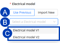
In the Design Inputs panel, select the
 Use Previous toggle under Electrical model.
Click the existing Electrical models
 dropdown.
Select one from the
 options.
The selected Electrical model will then be the  active Electrical model displayed below the dropdown. The date and time when it was first imported will also be displayed.
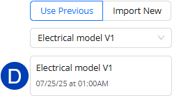
.png) When importing a new Electrical model into your study, your ACP Workspace must be launched from the Revit add-in because it takes the data directly from the active Revit project.
When importing a new Electrical model into your study, your ACP Workspace must be launched from the Revit add-in because it takes the data directly from the active Revit project.
Follow the steps below to import a new Electrical model into your study.
In the Design Inputs panel, select the
 Import New toggle under Electrical model.
Enter a
 Name and
  Description for the new Electrical model.
This helps easily identify the Electrical model version for use in different studies.
This is optional.
Click the
 Import Active Revit Project button.
If you’re doing this process from the web, the error message: Revit is not available, will appear at the top of your screen.
Please launch ACP from within your Revit project, and try again.
It may take several minutes to import the Electrical model.
Import or select the Background Geometry
If there’s an existing Background geometry within the ACP project where the study belongs, the latest version will be used for the current study by default, or you may Import Background Geometry from the Revit project.
Follow the steps below to use existing Background Geometry for the study or import new.
.png) To use existing Background Geometry for your study:
To use existing Background Geometry for your study:
In the Design Inputs panel, click the existing Background Geometry
 dropdown.
Select a Background geometry from the
 options.
The selected Background Geometry will then be the  active Background Geometry displayed below the dropdown.
The date and time when it was first imported will also be displayed..png)
When importing new Background Geometry into your study, your ACP Workspace must be launched from the Revit add-in because it takes the data directly from the active Revit project.
.png) Follow the steps below to import a new Background Geometry into your study.
Follow the steps below to import a new Background Geometry into your study.
In the Design Inputs panel, select the
 Import Active Revit Project button under Background geometry.
This button will be disabled if you’re accessing your ACP Workspace from the web.
The Import Background Geometry window will appear.
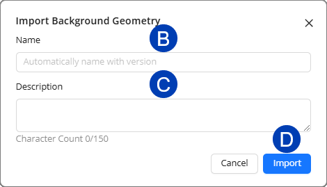 Provide a
  Name and
  Description for the Background Geometry.
This helps easily identify the Background Geometry version for use in different studies.
This is optional. If not specified, it will automatically be named following the format: Background Geometry version number, and the Description will be blank.
Click the
 Import button to proceed with importing the Background Geometry of the active Revit project.
Or Cancel to close the Import Background Geometry window and stop the process.
Set the Grid Resolution
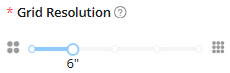 The Grid Resolution determines the size of the blocks into which ACP breaks down the entire site to analyze if each block of space is available or occupied. The size of the blocks may be set to 12”, 6”, 4”, 3”, and 2”.
To specify the Grid Resolution for the study, adjust the Grid Resolution slider to the preferred size.
Explore Design Inputs in the 3D Model Preview
The 3D Model Preview lets you explore the imported Electrical model and Background geometry prior to solution generation. For the first study in the ACP project, this view is initially blank but becomes populated as each Design Input is imported. At that point, the 3D Model Preview controls for each imported model are also enabled.
Customizing category display
Each part of the model has a corresponding View Control used to configure its visibility and display settings in the 3D Model Preview. The View Controls correspond to individual Revit categories, such as Electrical Fixtures and Electrical Equipment, or multiple categories commonly grouped together such as Floor Surfaces which is made up of floors, ramps, shaft openings, and stairs.
Using the view controls lets you show/hide categories, and change their color, transparency, and section cut behavior. This gives you more flexible control over the model during your review.
.png) Follow the steps below to control category visibility and display settings using the View Controls in the 3D Model Preview.
Follow the steps below to control category visibility and display settings using the View Controls in the 3D Model Preview.
Click the
 View Controls button. This will open the View Controls panel.
The categories are grouped into two sections: Background geometry and Electrical model.
Click the
 section headings to expand or collapse the section.
To show
.png) or hide
or hide .png) all categories in a View Controls section, click the Section Visibility toggle.
all categories in a View Controls section, click the Section Visibility toggle.If no Electrical model or Background geometry has been imported yet, the corresponding View Control will be disabled.
To show
.png) or hide
or hide .png) individual categories from view, click the Visibility toggle.
individual categories from view, click the Visibility toggle.If there are multiple Electrical models in the project, you can select which one to use in the
 Electrical model dropdown.
The Design Inputs panel will be updated with the selected Electrical model.
The selected Electrical model will then be used as basis for generating solutions.
Modify how each category is displayed in terms of color and transparency.
To change the color of a category, click the
 Color Selector then pick a color from the
  pop-up.
To make a category transparent
.png) or solid
or solid .png) (default), click the Transparency toggle.
(default), click the Transparency toggle.
To exclude a category from being cut by Section Planes or the Section Slider, click the Section toggle to turn it off
.png) .
.Otherwise, leave the Section toggle on
.png) .
.
Viewing model cross-section
Cutting through the model shows its cross-sectional area, allowing for a more detailed review of its interior. To cut the model, you can either use Section Planes or the Section Slider.
Section Planes
Here’s how you can use Section Planes in the 3D Model Preview.
.png)
Position the model so the plane you want to section through is displayed.
You can use the
 View Cube or other navigation controls.
Click the
 Section Planes button.
.png)
Click the
 Add Section Plane button.
When the
 banner at the top appears, click the point in the model where you want to place the section plane.
After placing the section plane, you can use the
 section plane controls to do the following:
 Adjust the depth of the plane using the straight arrows. Click drop-down to view animation.
 Hover your mouse cursor over the straight arrow corresponding to the plane you want to adjust.
When the arrow is selected, click and drag to the preferred depth.
Rotate the plane to change its orientation using the double-headed arcs. Click drop-down to view animation.
 Hover your mouse cursor over the arc corresponding to the plane you want to rotate in.
When the arc is highlighted, click and drag to rotate the plane to the preferred orientation.
Repeat the previous steps to add more section planes in the model.
button.
Section Slider
The Section Slider on the left-hand side of the 3D Model Preview allows you to horizontally cut the entire model, making it quicker to view the top and bottom cross-sections at any elevation.
Click and drag the top and bottom handles of the Section Slider to horizontally section the model. The tooltip dynamically displays the elevation from the ground at which the model is cut as you adjust the slider. Click drop-down to view animation.
.gif)
Next steps
Once you’ve completed these steps, you may proceed with setting design rules for the study.