Opening an existing Study or creating a new one opens the Study view interface. This is where users can Import and manage the necessary data for ACP to Generate conduit routing solutions from the study.
Study view controls
The controls in the Study view interface lets users manage study information and move the study into the different stages of the ACP workflow.
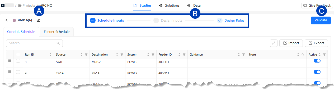
 Edit Study Summary button - Accesses the Edit Study Summary window where users can update the Name and Description of the study.
 Study view sub-tabs - Navigates to each of the three sub-tabs: Schedule Inputs, Design Inputs, and Design Rules.
 Each one provides a platform to import, manage, and configure data necessary to generate solutions.
Each Tab will display a status during the study creating process
Grayed out ellipsis
 : This tab contains steps that have not been completed. Click the tab and complete the missing steps.
 Red X Icon
 : This tab contains data with errors. Click on the tab to view and resolve the errors.
 Blue Checkmark
 : This tab has all required data entered and is ready for validation.
 Study actions - Initiates the different processes that a study goes through until solutions are generated.
Initially, it displays the Validate button
 which starts the process of verifying that the Design inputs match the Schedule Inputs.
 When the study’s status is Valid & Ready, the Validate button becomes Generate
 which starts the process of generating solutions for the study.
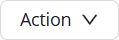
 After solutions have been generated, the Action dropdown
 and View Solutions button
  will replace the Generate button.
The Action dropdown
contains the options to: View Model, View Solutions, Duplicate, Archive, Edit Summary, and Delete.The View Solutions button
navigates to the Solutions tab which is already filtered by the current study.
Schedule Inputs
The Schedule Inputs sub-tab in the Study view is where you can define the Raceway information that ACP needs to generate solutions. This includes specifying the Source and Destination, the size and number of parallel runs, and the System name.
Because ACP pulls the Source and Destination information directly from the Revit project, ACP must be launched from within the correct Revit project for this feature to be enabled.
If ACP is accessed from a web browser, the following message will display within the Schedule Inputs interface, and the schedule table will be grayed out:
Schedule Inputs Interface
The Schedule Inputs sub-tab of the Study view is where the Conduit Schedule and Feeder Schedule can be created. The controls listed below are the same for both the Conduit Schedule and Feeder Schedule.
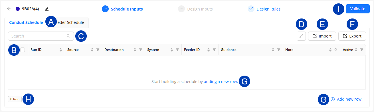
 Conduit Schedule/ Feeder Schedule tabs: Toggles the view between the Conduit Schedule and the Feeder Schedule for the current study.
 .png) Schedule table: Contains all of the rows for the Conduit Schedule and the Feeder Schedule for the current study.
Schedule table: Contains all of the rows for the Conduit Schedule and the Feeder Schedule for the current study. .png) Search: Filters visible Run IDs by matching the entered text against all fields in the current schedule.
Search: Filters visible Run IDs by matching the entered text against all fields in the current schedule..png)
.png) View Density: Allows switching between Medium and Compact size of the Projects table for easier viewing.
View Density: Allows switching between Medium and Compact size of the Projects table for easier viewing. .png)
.png) Import: Used to bring in external Conduit Schedule and the Feeder Schedule data for the study:
Import: Used to bring in external Conduit Schedule and the Feeder Schedule data for the study:Import Previous Schedule - Transfers schedule data created in a different study into the current one.
Import CSV/XLSX - Imports schedule data from an external CSV or XLSX file using mapped headers.
.png) Export: Generates a new CSV file containing the current schedule data.
Export: Generates a new CSV file containing the current schedule data..png) Add New Row: Creates a new, blank row in the active schedule for manual input.
Add New Row: Creates a new, blank row in the active schedule for manual input. .png) : Will appear within a blank schedule.
: Will appear within a blank schedule.
.png) Counts: Displays the total number of Run IDs
Counts: Displays the total number of Run IDs .png) and any Errors/Warnings
and any Errors/Warnings .png) present in the schedule, regardless of filters or active status.
present in the schedule, regardless of filters or active status.Clicking the Errors button
takes you to the first error to be fixed, and pressing it multiple times cycles through each error in order.
.png) Validate: Checks the data from all of the imported inputs (including the ACP created Schedule Inputs) to ensure data alignment.
Validate: Checks the data from all of the imported inputs (including the ACP created Schedule Inputs) to ensure data alignment.
Schedule controls
Below are the table controls in the Conduit Schedule and Feeder Schedule tabs.
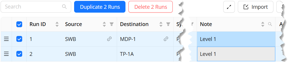 Select run(s): Allows user to select one, multiple, or all Run IDs/Rows within the schedule
 .png)
Duplicate: Create an exact duplicate of the selected Row(s), with a the next specified Run ID.
Delete: Delete the selected Row(s) from the schedule.
Modify a field: Update any of the data of a selected row(s)
When multiple rows are selected in a schedule, any data entered in one field, will automatically apply to all selected rows.
Select all: The checkbox in the top left hand corner of the schedule (next to the schedule headers).
Click to select all rows within the table to duplicate, delete, or modify a field for all.
.png)
Move: Click to drag the row to a different location within the table.
.png)
Sorting: Sorts all rows in the table by either the ascending or descending order of the column’s values.
.png)
Filtering: Enables users to filter the table view based specific rows in the list based on selected values in the column.
.png)
Note Search: Filters visible Run IDs by matching the entered text against the Note field in the current schedule.
.png)
Link to Element
.png) : Functions similarly to Revit’s Highlight in Model
: Functions similarly to Revit’s Highlight in Model .png) feature, allowing you to locate the corresponding element in the Revit model from the Source and Destination fields.
feature, allowing you to locate the corresponding element in the Revit model from the Source and Destination fields.Error Display: Hovering over the red icon
 displays the full error message along with suggestions for resolution.
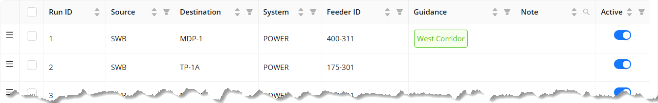
Conduit Schedule columns
Specifies the information about each Raceway from a Source to a Destination within the project.
Column Header | Description | Additional Notes |
|---|---|---|
Run ID | Unique identifier for each row representing a specific source and destination between which conduit should be run. | Any unique combination of letters, numbers, and symbols. ACP will auto-step the next row based on the last digit of the previous Run ID.
|
Source | The name of Electrical Equipment (Panel Name) or Electrical Fixture (ACP_E_Fixture ID) where the conduit originates. | A dropdown list populated by Electrical Equipment and Electrical Fixture elements in the active Revit project. |
Destination | The name of the Electrical Equipment (Panel Name) or Electrical Fixture (ACP_E_Fixture ID) where the conduit terminates. | A dropdown list populated by Electrical Equipment and Electrical Fixture elements in the active Revit project. |
Feeder ID | References the Feeder ID from the Feeder Schedule | The Feeder Schedule must be correctly populated prior to assigning the Feeder ID, as this column is a dropdown list populated by the Feeder ID column in the Feeder Schedule. |
System | Identifies the power system associated with the conduit | Any combination of letters, numbers, and symbols. This input may also be used in the ACP process to assign a system scope to Design Rules. |
Guidance | References one or more named Preferred Boxes assigned to the corresponding Run ID. This will force the conduits associated with the Run ID to enter the box at some point of the route. | The Preferred box much be placed within the model, and given a name using the ACP_C_Guidance_Box_Name parameter, prior to being able to assign it to the corresponding Run ID. |
Note (optional) | A field for capturing additional information related to the Run ID. | This can include grouping information or study-specific context. This field may be left blank. |
Active | Determines if a Run ID should be routed within the current ACP study. | On Off |
Feeder Schedule columns
Provides the conduit schedule with the information about the size and number of conduit runs for each Run ID by referencing the Feeder ID field.
.png)
Column Header | Description | Additional Notes |
|---|---|---|
Feeder ID | A unique identifier for each set of feeders to be installed. | Any unique combination of letters, numbers, and symbols. |
Parallel Runs | The number of conduits that will run in parallel between the source and the destination to carry the required feeders. | Any positive integer. |
Conduit Size | The nominal diameter of the conduit(s) used to carry the set of feeders from the source to the destination. | Choose from the pre-programmed drop-down list of ACP-supported conduit sizes. |
Design Inputs
The Design Inputs sub-tab is where users can import, select, and explore the 3D models to be used for the study. This is also where the study’s Grid Resolution is set.
It’s divided into two sections:  Design Inputs panel and the
  3D Model Preview.
.png)
Design Inputs panel
The Design Inputs panel is where the Electrical Model and Background Geometry may be imported, and where the Grid Resolution may be set.
 Validation status - A status pop-up which indicates that the Electrical Model and Background Geometry in the study are ready for validation.
The validation status doesn’t mean that all study inputs are ready for validation. You may still need to build your schedules and/or configure design rules.
 Import Electrical model - Select an Electrical model to be used for generating solutions. You can either Use Previous or Import New.
 .png)
This option allows you to select an existing Electrical model within the ACP Project. For this reason, it’s not required to launch the ACP Workspace from the Revit add-in to use this option.
Existing Electrical models dropdown -
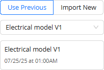 Contains all Electrical models previously imported into the ACP project from which you can select one to use for the study.
Active Electrical model - Displays the name of the active Electrical model, if already selected, as well as the date and time when it was imported into the ACP.
This option requires the ACP Workspace to be launched from the Revit add-in.
.png) Name - The name that the Electrical model will be referred as once it’s imported into ACP.
Name - The name that the Electrical model will be referred as once it’s imported into ACP.Description - The description of the Electrical model once it’s imported into ACP.
Import Active Revit Project button - Imports the Electrical model from the active Revit project.
Import details - Displays the date and time when the Electrical model has been imported into the study.
 Import Active Revit Project (Background geometry) - Imports the Background geometry from the active Revit project. Your ACP Workspace must be launched from the Revit add-in to use this option.
 Existing Background geometry dropdown - Contains all Background geometry previously imported into the ACP project from which you can select one to use for the study. Using this option does not require launching your ACP Workspace from the Revit add-in.
 Active Background geometry details - Displays the name of the Background geometry currently selected for the study, if any, as well as the date and time when it was imported into ACP.
 Grid Resolution slider- Allows users to determine the size of blocks (12”, 6”, 4”, 3”, or 2”) by which ACP will divide the project space for obstruction analysis and routing optimization.
3D Model Preview
.png) The 3D Model Preview lets you explore the Electrical model and Background geometry imported into the study prior to solution generation.
The 3D Model Preview lets you explore the Electrical model and Background geometry imported into the study prior to solution generation.
 Background Geometry Info - Displays the name of the active Background geometry and when it was imported into the study.
 View Controls - Contains the visibility settings for the elements in the imported models. The view controls in the 3D Model Preview are grouped into two: Background geometry and Electrical model.
  Expand/Collapse toggle - Expands or collapses the view control section.
  View control group visibility toggle - Show
 .png) or hide
or hide .png) all View Controls within the group.
all View Controls within the group.  View control visibility toggle - Show
 .png) or hide
or hide .png) the parts of the model controlled by the corresponding View Control.
the parts of the model controlled by the corresponding View Control. Color selector - Change the color of the parts of the model controlled by the corresponding View Control.
 Transparency toggle - Controls if the corresponding elements/categories are solid
 .png) or transparent
or transparent .png) .
. Section cut toggle - If turned on
  , the corresponding category will be cut off by section planes or the Section Slider. If turned off
 .png) , the category will be excluded from the cut.
, the category will be excluded from the cut. Electrical model selector - Change the Electrical model displayed in the preview into any Electrical model imported into any study within the same project.
 Section Planes - A tool used to cut through the 3D model to show it’s cross-section.
 View Cube - A navigation tool which lets you easily switch views of the 3D model by clicking or dragging its labeled faces, edges, and corners.
 Vertical section slider - Drag the top and bottom handles to create a horizontal section of the model.
Design Rules
The Design Rules sub-tab displays the rules within the study. The Design Rules panel on the left-hand side lists all the design rules and constraints, while the right-hand side is the Design Rules viewer which displays either the Design Rules table or the Design Rule settings.
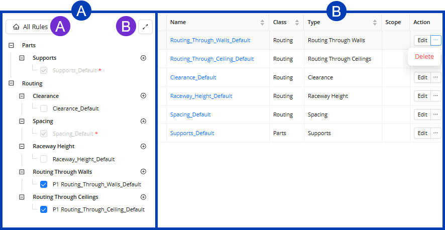
 Design Rules panel
 All Rules: Displays all Design Rules in the viewer.
  View Density toggle: Allows switching between Medium and Compact size of the Design Rules table.
Design Rule checkbox: When checked, this enables that design rule to be applied to the study.
When unchecked
 , the rule is disregarded during the generation of solutions.
Create rule button
 - Initiates creating a design rule for the corresponding design rule type.
 Design Rules viewer
The Design Rules viewer shows either the Design Rules table or the Design Rule settings.
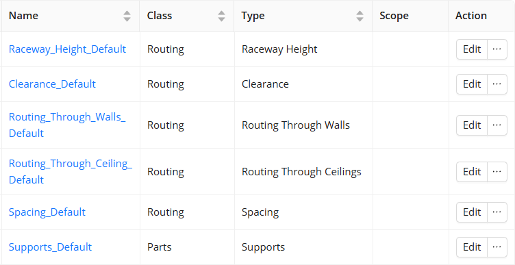 The Design Rules table displays all design rules for the selected Design Rule type. It has the following columns:
Name: Provides the default or user-created names of the Design Rule.
Class: Displays the ACP classification type impacted by the Design Rule.
Type: Shows the Design Rule type for which the design rule is applied.
Scope: Presents the region of the site where the Design Rule would be applied.
Action: Provides the ability to Edit or Delete the Design Rule.
.png)
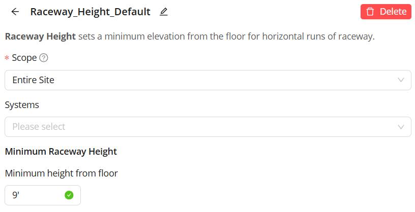 The displayed Design Rule settings will vary depending on the design rule type being created.
All settings use dropdowns, textboxes, and/or toggle switches.
Dropdown - Contains all possible values from which you can choose a value for the field.
These have a down arrow on the right side of the field, and is used for the following:All Design Rules: Select a Scope for which to apply the design rule.
Supports Design Rule: Select a Support Spec which can be used for the study.
Clearance and Raceway Height design rules - Select the Systems for which to apply the design rule.
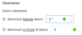 Textbox - Allows users to manually enter measurements for Clearance, Spacing, and Raceway Height design rules. Up and down arrows used to increase or decrease the measurement appear on the right side of the field when you hover your mouse cursor over the textbox.
Toggle switch - Enable
 or disable
  the Routing Through Walls and Routing Through Ceilings design rule types.