The 3D Solution Viewer in the ACP Workspace provides users with a robust interface for analyzing and interacting with ACP generated conduit routing solutions. It allows for review of conduit placements, Electrical Model, and Background Geometry using visualization tools such as Placement Considerations, View Controls, Section Planes, and Bookmarks.
Refer to the Navigating the 3D Solution Viewer interface article for a complete description of all tools and navigation elements in the 3D Solution Viewer. This article focuses specifically on reviewing routing outcomes using the 3D Solution Viewer.
Open a solution in the 3D Solution Viewer
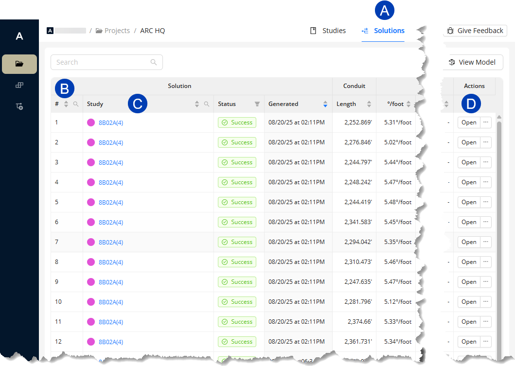 ACP generates 12 unique solutions for each study in your ACP project. All solutions are listed by study in the table within the
  Solutions tab. To differentiate the solutions, they are assigned a
  number from 1 to 12.
To open a solution in the 3D Solution Viewer from the Solutions table:
Click the
 study name.
 Or click the
 Open button corresponding to the solution under the Actions column.
PRO TIP: Because 12 unique solutions are generated for each study, the table can easily grow up to hundreds of rows. To display only the solutions for a specific study:
Navigate to the
Studies tab.
Open the study used to generate the solution you want to review.
Click the
View 12 solutions button at the top right corner.
This switches you to the Solutions tab and automatically filters the table to the selected study.
Changing the solution color
.png) When you open any solution in the 3D Solution Viewer, a default color
When you open any solution in the 3D Solution Viewer, a default color .png) is assigned to it. The solution color may be changed to any color you prefer. This color will be used to display any solution you open throughout the session. The color resets to the default for each new session.
is assigned to it. The solution color may be changed to any color you prefer. This color will be used to display any solution you open throughout the session. The color resets to the default for each new session.
Follow the steps below to change the solution color in the 3D Solution Viewer.
Click the
 color selector.
Select a color from the
 dropdown.
Changing the displayed solution
.png) The solution displayed in the 3D Solution Viewer may be changed at any time.
The solution displayed in the 3D Solution Viewer may be changed at any time.
Follow the steps below:
Click the
 solution name dropdown at the top left corner.
From the
 dropdown list, select the study.
Select the
 solution from the list next to the study dropdown.
Control the model display
Each part of the model has a corresponding View Control used to configure its visibility and display settings in the 3D Solution Viewer. The View Controls correspond to individual Revit categories, such as Electrical Fixtures and Electrical Equipment, or multiple categories commonly grouped together such as Floor Surfaces which is made up of floors, ramps, shaft openings, and stairs.
These View Controls allow for more flexibility and control as you review a solution in the 3D Solution Viewer. You can change the Background Geometry version, show or hide categories, and customize how each category is displayed.
.png) Changing Background Geometry version
Changing Background Geometry version
In the 3D Solution Viewer, you can overlay the generated solution in different versions of the Background Geometry.
Here’s how:
Click the
.png) View Controls button.
View Controls button. Expand the
.png) Show Background Geometry group.
Show Background Geometry group.Click the
.png) dropdown right below the section heading.
dropdown right below the section heading.Select the preferred background geometry from the
.png) options.
options.
Because Background Geometry influences supportability and defines obstructions to be routed around, overlaying geometry other than that used for the current study will not accurately represent their interaction and should be viewed only as a basis for comparison.
.png) Showing/Hiding categories
Showing/Hiding categories
View Controls are grouped into four sections: Show Background Geometry, Visualizations, Electrical, and Bookmarks. Visibility may be set either as a group or individually.
Follow the steps below to configure what’s visible in the model using the View Controls.
Click the
.png) View Controls button.
View Controls button. The View Controls panel will appear.
All View Controls sections are enabled
 by default.
To hide an entire View Controls section, click the corresponding
.png) toggle switch to disable
toggle switch to disable  it.
it. To configure view controls individually,
Click the View Controls section
.png) heading to expand it.
heading to expand it.Locate the view control you want to configure.
Click the
.png) visibility toggle to enable or disable it.
visibility toggle to enable or disable it. The model in the 3D Solution Viewer will update as you show
 or hide
  the view control.
Customizing category display
Each View Control has three display settings which control its color, transparency, and section cut behavior.
.png) Color
Color
Each category in the model has an assigned default color. For ease of identification, especially in large models, you may change this color to your preference.
Follow the steps below to change a category’s color.
In the View Controls panel, locate the view control corresponding to the category and click its
 Color Selector.
Select your preferred color from the
 pop-up.
 The specific
 part of the model will be updated accordingly.
The color shading adjusts to perspective. It may appear darker or lighter depending on the model’s orientation.
 Transparency
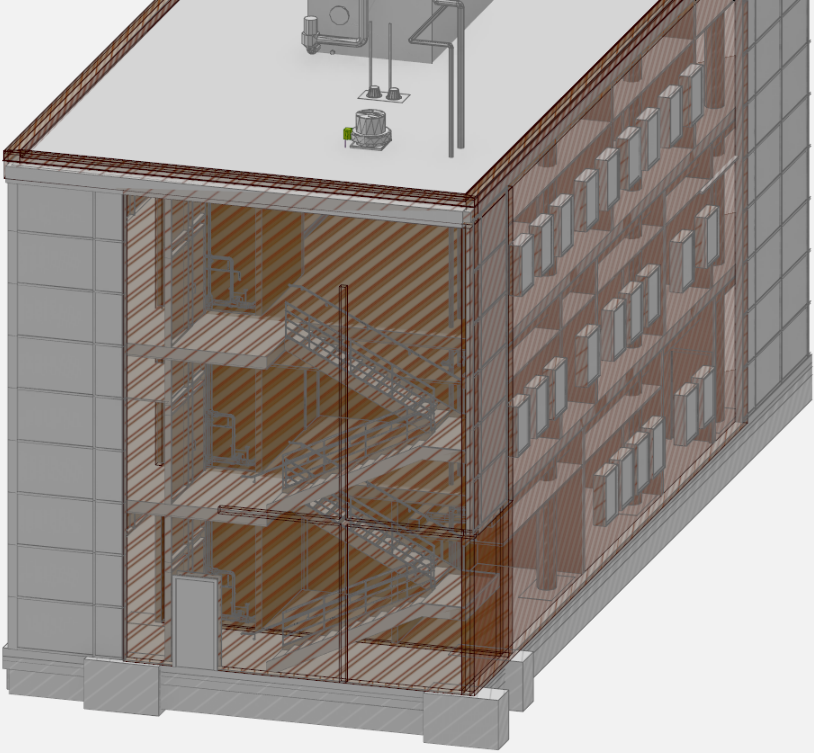
By default, the faces of all categories, except those under Visualizations, are drawn solid. This makes it impossible to review the internal structure of the building or a category without cutting through it.
Click the Transparency toggle of a category’s view control to make it transparent
 or solid
  .
. The example on the right shows transparent Exterior Walls, making the interior of the building visible.
 Section cut behavior
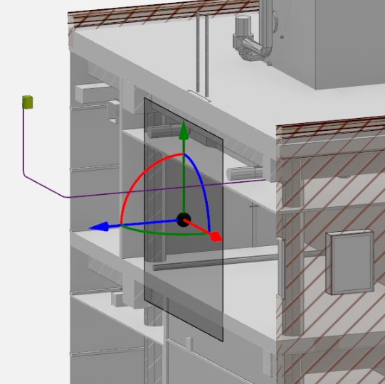
When modifying the view with section planes, all of the elements in front of the section plane are cut. To exclude specific parts from being cut, click the corresponding Section toggle ![]() . By default, the Section toggles for all Electrical view controls are turned off. In the image on the right, the solution
. By default, the Section toggles for all Electrical view controls are turned off. In the image on the right, the solution .png) and Electrical Equipment
and Electrical Equipment  are excluded from being cut by the section plane.
Restore default view control settings
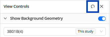 The view control settings are maintained throughout the session, even when you exit the 3D Solution Viewer or change the displayed solution. This makes it easier to review different solutions in the same context. There are two ways to restore the default view control settings:
Click the Reset button in the View Controls panel.
Or restart the session.
View the model cross-section
Cutting through the model allows you to view its cross-sectional area, allowing for a more detailed review of how conduits were routed in certain regions of the model. To cut the model, you can either use the Section Planes or Section Slider.
.png) Using Section Planes
Using Section Planes
Placing section planes
The steps below outline how you can add a section plane, and adjust its position.
Position the 3D model so the plane you want to section through is visible.
You can use the
.png) View Cube or the navigation controls.
View Cube or the navigation controls.
Click the
.png) Section Planes button.
Section Planes button. The Section Planes pop-up will appear.
In the Section Planes pop-up, click the
.png) add button.
add button.When the
.png) banner appears at the top, click on a surface of the model where you want to place the section plane.
banner appears at the top, click on a surface of the model where you want to place the section plane.After placing the section plane, you can use the section plane controls to do the following:
Adjust the depth of the plane using the straight arrows. Click drop-down to view animation.
 Hover your mouse cursor over the straight arrow corresponding to the plane you want to adjust.
When the arrow is selected, click and drag to the preferred depth.
Rotate the plane to change its orientation using the arcs. Click drop-down to view animation.
 Hover your mouse cursor over the double-headed arc corresponding to the plane you want to rotate in.
When the double-headed arc becomes a circle, click and drag to rotate the plane to the preferred orientation.
Repeat the previous steps to section more planes in the model.
Deleting Section Planes
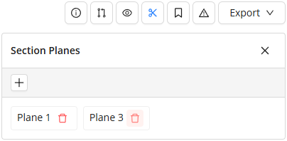 When Section Planes are no longer needed in the viewer they can be easily deleted.
Click the Section Planes button.
The Section Planes pop-up will appear.
Click on the Trash button
 next to the section plane you want to delete.
However, these settings are not saved with the project. If you close your ACP Workspace or exit the project, all visibility settings (including Section Planes) will be deleted.
Using the Section Slider
The Section Slider on the left-hand side of the screen allows you to horizontally cut the entire model, making it quicker to view the top and bottom cross-sections at any elevation.
Click and drag the top and bottom handles of the Section Slider to horizontally section the model. The tooltip dynamically displays the elevation from the ground at which the model is cut as you adjust the slider. Click drop-down to view animation.
Explore Placement Considerations
The Placement Considerations panel highlights problem areas in the solution. This panel is divided into two tabs:
Unrouted Runs - Highlights conduit runs which ACP wasn’t able to route.
Parts - Bends which ACP can’t construct.

PRO TIP:
Type the name of a Source or Destination in the search bar within the Unrouted Runs tab to search for all related unrouted runs.If there are no results, all runs for that element have successfully been routed.
Reviewing unrouted runs
.png) Unrouted Runs are Run IDs from your Conduit Schedule which ACP wasn’t able to route. Reviewing unrouted runs in the 3D Solution Viewer allow you to determine where modifications may be made in the model for successful routing.
Unrouted Runs are Run IDs from your Conduit Schedule which ACP wasn’t able to route. Reviewing unrouted runs in the 3D Solution Viewer allow you to determine where modifications may be made in the model for successful routing.
Follow the steps below.
Click the
.png) Placement Considerations button.
Placement Considerations button. By default, the Placement Considerations panel will open to the Unrouted Runs tab listing all conduit runs which couldn’t be placed in Source-Destination format.
Select any
.png) Source-Destination pair to display the Run ID Information Panel containing the following:
Source-Destination pair to display the Run ID Information Panel containing the following:Details of the selected run
.png) Reason why the run couldn’t be placed and how to potentially resolve it
Reason why the run couldn’t be placed and how to potentially resolve itThe
.png) Source for the Run ID
Source for the Run IDClick on the source name to zoom in to it.
PRO TIP: To avoid walls blocking the view when you zoom to the element, use the View Controls to hide .png) Exterior Walls and Interior Wall Items. It may also help to make some categories transparent
Exterior Walls and Interior Wall Items. It may also help to make some categories transparent .png) .
.Note the spherical target over the element.
The
.png) Destination for the Run ID
Destination for the Run IDClick on the source name to zoom in to it.
Note the spherical target under the element.
The
 Show Explored Run ID toggle controls whether to hide or show the visualization of areas that ACP explored as possible (supportable) route for the Run ID.
 This appears as a translucent blue shading in the model.
A
 straight line connecting the Source and the Destination
Using the tools listed above, explore the the solution to look for clues about why the Run ID was unable to be routed.
Here are some common reasons conduits may not route:Obstructions
Collision geometry which fully blocks any possible route between a Source and Destination.
Panel Fill
Electrical Equipment that has no additional room for conduits on the routable faces.
Supportability
Conduit racks that cannot be fully supported within the model.
Click here for steps to view if the area around the Source and Destination is supportable.
.png) Click
Click  View Controls.
In the View Controls panel, expand the
 Visualizations section.
Enable the
 toggle switch for any Supportable Volumes category, i.e. Overhead, Wall, and Floor, to visualize its supportability.
Overhead - Shows the supportable volume from the floor above until the nearest obstruction below, such as ceilings.
Wall - Highlights the area within a specific distance from walls which is supportable.
Floor - Highlights the supportable parts of floors based on Floor Supports in the specification.
This workflow is not typical, so this setting would not usually be used.
Pro Tip:
To give yourself more room in the 3D Solution Viewer, close the Placement Considerations panel, while leaving the Run ID Information panel open. Both windows will close, but the selected source-destination pair, will still be highlighted in the Viewer.
.png) Reviewing Unknown Parts
Reviewing Unknown Parts
ACP searches for available space and a supportable path for the conduit solution before placing the individual components of the Conduit Run. Sometimes, while building the run, ACP may encounter a bend it can't determine how to construct. Instead of failing the entire route, it places an element called an Unknown Part where the bend should be. These Unknown Parts are included when the conduit solution is exported to Revit, making it easy for you to locate and update the solution with the correct bend.
Follow these steps to review these Unknown Parts:
Click the
.png) Placement Considerations button.
Placement Considerations button. The Placement Considerations panel will open to the Unrouted Runs by default,
Switch to the
.png) Parts tab where all the Unknown Parts are listed.
Parts tab where all the Unknown Parts are listed.Click any part in the list to zoom in to its location and display the
.png) Run ID information panel containing the following details:
Run ID information panel containing the following details:Part type(s) tried
Source(s)
Destination(s)
The section of the conduit run where ACP couldn't find a matching part will appear in
.png) orange. This issue may not occur in other solutions where the conduit run takes a different path. Use the
orange. This issue may not occur in other solutions where the conduit run takes a different path. Use the .png) dropdown in the top-left corner to switch solutions and check if the missing part is resolved.
dropdown in the top-left corner to switch solutions and check if the missing part is resolved.
When Unknown Parts are exported to your Revit project with the conduit solutions, they are placed using a Generic Model family. Currently, this family does not automatically contain a specific identifier, including Family name or Type name. They can be identified within a schedule because the Family name and Type name will be blank.
Work with Bookmarks
Bookmarks allow you to save data about and a specific view of an area within the solution. This can be useful for tracking specific parts of the solution that may require more attention or that your team wants to track in the project.
This section covers how you can create, show, navigate to, and update bookmarks.
Creating a Bookmark
 Navigate to the location in the 3D model where you want to place a bookmark and position it in the view angle you want to capture.
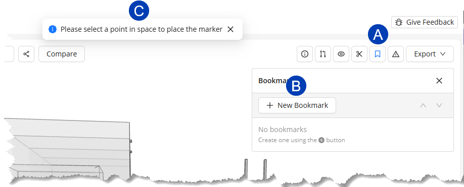
Click the
.png) Bookmark button.
Bookmark button.In the Bookmark panel, select the
.png) New Bookmark button.
New Bookmark button.When the
.png) banner appears at the top, click the point in the 3D model where you want to place the bookmark.
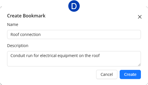
banner appears at the top, click the point in the 3D model where you want to place the bookmark.In the
.png) Create Bookmark pop-up, enter a Name and Description.
Create Bookmark pop-up, enter a Name and Description.Click the Create button. The bookmark will be placed on the model.
Generate Link button in the top right hand corner of the bookmark information panel.
This will automatically save the shared URL to your clipboard ready to be shared.
Controlling bookmark visibility in the 3D Solution viewer
Bookmarks appear as .png) labels in the 3D model.
labels in the 3D model..png) The color of these labels is inherited from the solution color set in the 3D Solution Viewer.
The color of these labels is inherited from the solution color set in the 3D Solution Viewer.
Bookmarks may be hidden in one of two ways: Using the Bookmarks toggle in the View Controls panel (hides all bookmarks together), or individually within the Bookmark panel.
Follow the steps below to turn on/off the visibility of the bookmarks.
.png) Hide/Unhide ALL bookmarks in the solution
Hide/Unhide ALL bookmarks in the solution
Click the
.png) View Controls button.
View Controls button.Scroll to the bottom of the View Controls panel.
Use the toggle switch for
.png) Bookmarks to make ALL of the bookmarks in the solution visible nor not visible.
Bookmarks to make ALL of the bookmarks in the solution visible nor not visible.
Hide/Unhide individual bookmarks in the solution.
.png) Click the
Click the  Bookmark button.
In the Bookmark panel, click the corresponding
 visibility toggle to show
 .png) or hide
or hide .png) a bookmark.
a bookmark.
Reviewing an existing Bookmark
You can navigate to a bookmark from the Bookmark panel or via a Bookmark label:
.png) Click the
Click the .png) Bookmark button in the top righthand corner of the 3D Solution Viewer .
Bookmark button in the top righthand corner of the 3D Solution Viewer . This will open the
.png) Bookmark panel.
Bookmark panel.
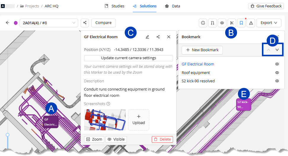
In the Bookmark panel, click on the bookmark you want to view.
The 3D Model Viewer will zoom in to where the bookmark was placed.
The
.png) Bookmark Information panel for bookmark will be opened.
Bookmark Information panel for bookmark will be opened.
Review the Bookmark Information panel for more details about the bookmark.
Description
Uploaded Screenshots
Camera position
Update controls.
Navigate to a different bookmark in one of three ways:
Select a different bookmark from the list in the Bookmark panel.
Use the
.png) up and down buttons in the Bookmark panel to navigate to the previous or next, respectively, bookmark.
up and down buttons in the Bookmark panel to navigate to the previous or next, respectively, bookmark.Select a different
.png) Bookmark Label within the 3D Solution Viewer.
Bookmark Label within the 3D Solution Viewer.
Click on a
 Bookmark Label within in the 3D Solution Viewer.
 This will open the
 Bookmark panel, as well as the
  Bookmark Information panel for that bookmark.
Review the Bookmark Information panel for more details about the bookmark.
Description
Uploaded Screenshots
Camera position
Update controls.
Navigate to a different bookmark in one of three ways:
Select a different bookmark from the list in the Bookmark panel.
Use the
up and down buttons in the Bookmark panel to navigate to the previous or next, respectively, bookmark.Select a different
 Bookmark label within the 3D Solution Viewer.
Bookmarks are saved to a specific Solution and will not be visible in any other Solution or Study.
The Bookmarks column in the Study List shows which Studies contain Solutions with bookmarks.
Click the Bookmark button
to open the Bookmarks window, where you can view details about individual bookmarks (including which Solution they belong to), and to view them in the 3D Solutions Viewer.
Updating an existing Bookmark
In the Bookmark information panel, you can update the bookmark’s Name, Description, and camera and visibility settings.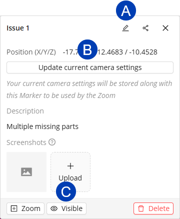
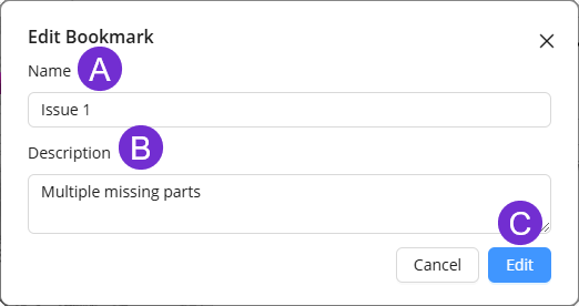
Updating the bookmark’s Name and Description
Click the
 Edit Bookmark button.
 Update the
 Name and
  Description as preferred.
Click the
 Edit button.
Or select Cancel to exit the Edit Bookmark pop-up without saving your changes.
Updating the view in which the bookmark is shown,
Use the navigation controls to adjust the model to show the preferred view.
Click the
 Update current camera settings button. The bookmark will be shown in this view the next time you navigate to it.
Controlling Visibility of a Bookmark in the Bookmark Information panel
Use the
 visibility toggle at the bottom of the Bookmark Information panel to make the bookmark Visible
 .png) or Hidden
or Hidden .png) in the model.
in the model.
Managing screenshots of a Bookmark
Provide additional context by adding screenshots of different camera angles around the bookmarked element.
Here’s how you can upload, view, and delete screenshots associated with a bookmark.
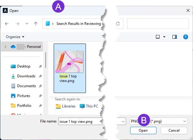
Uploading screenshots
Click the
 Upload button.
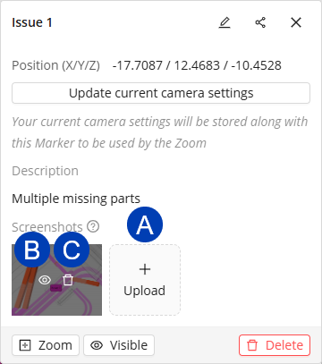
In the
 pop-up file manager window, navigate to and select the screenshot you want to upload.
Click the
 Open button.
 Repeat the steps to upload multiple screenshots.
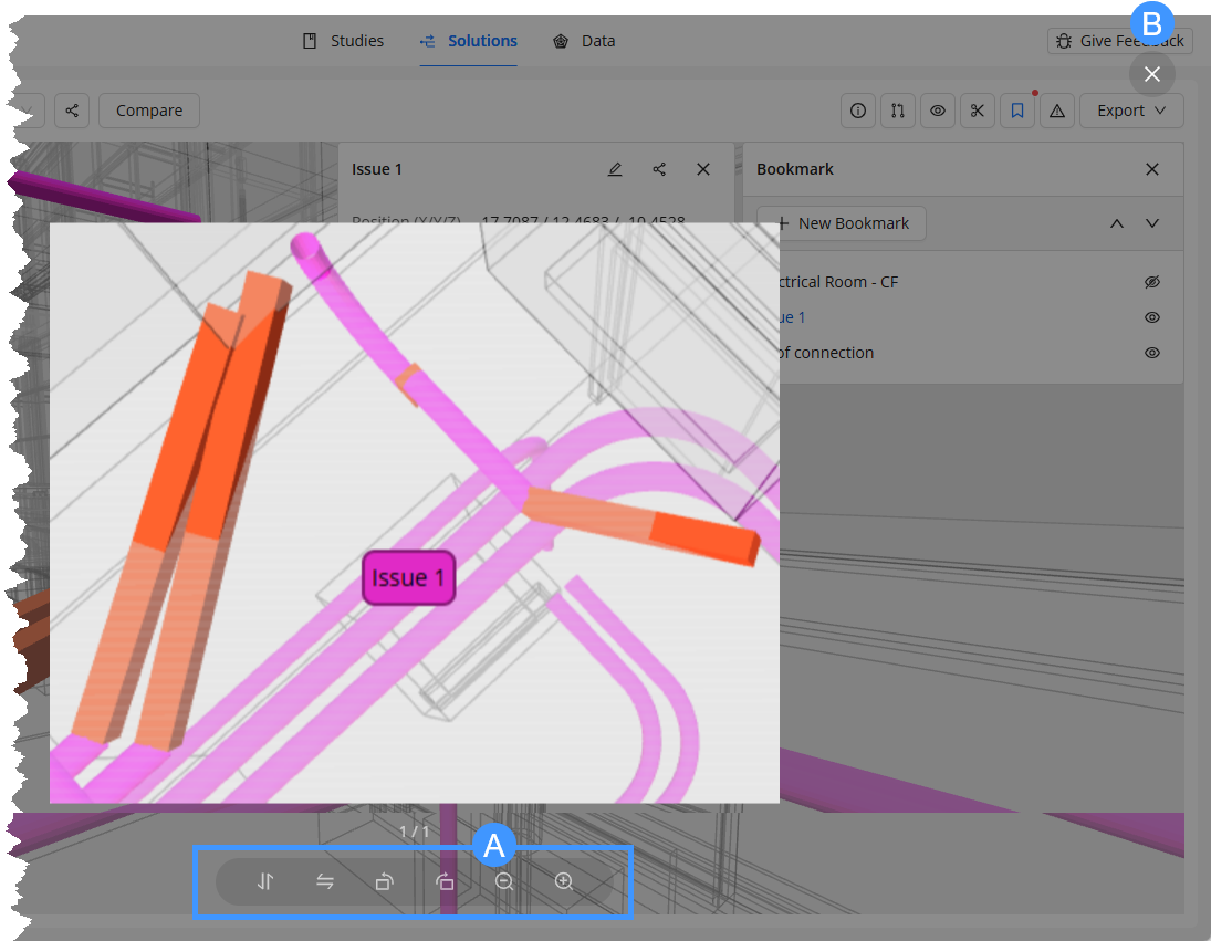
Opening the screenshot in the image viewer
Hover over the screenshot.
Click the
 show button.
The
 controls of the image viewer are at the bottom. You can flip the image horizontally and vertically, rotate it clockwise or counterclockwise, and zoom in and out.
Use the
 exit button to close the image viewer.
Deleting the screenshot
Hover over the screenshot.
Click the
 Delete button.
Compare solutions
ACP generates 12 routing solutions for each study. Within the 3D Solution Viewer, you can compare any two solutions side-by-side. The two solutions are identified as Primary Solution and Secondary Solution.
Primary Solution - The active solution in the 3D Solution Viewer. This solution defines the viewer context such as Placement Considerations, Background geometry, Electrical model, and Visualizations.
Secondary Solution - Displayed as a read-only overlay, allowing you to compare its conduit routes with those in the First Solution.
You can enter the compare solution mode in two ways:
.png) In your ACP project’s
In your ACP project’s  Solutions tab, you can enter the solution compare mode and select two solutions. Follow the steps below.
Click the
 Compare button at the top.
Use the
 Filter studies button to filter the table to show only solutions you’d like to compare.
You can compare any two solutions, whether they're from the same study or different studies.
Select the
 checkboxes corresponding to the two solutions you’d like to compare.
 The first solution you select becomes the
 Primary Solution and the next becomes the
  Secondary Solution.
The selected solutions will be displayed at the top.
If you’d like to switch the Primary Solution and Secondary Solution, click the swap
.png) button.
button. Click the
 Confirm button at the top right corner.
This opens the selected solutions in solution compare mode within the 3D Solution Viewer.
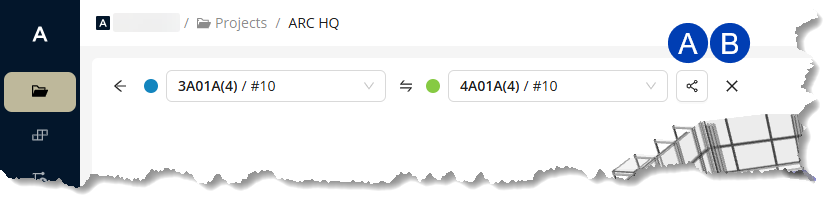
.png) From within the 3D Solution Viewer, you can enter the solution compare mode by following the steps below:
From within the 3D Solution Viewer, you can enter the solution compare mode by following the steps below:
Click the
 Compare button at the top.
Your active solution in the 3D Solution Viewer becomes the Primary Solution.
To change the Primary Solution, click the
 Primary Solution dropdown and select a study then solution from the list.
To select the Secondary Solution, click the
 Secondary Solution dropdown button and select a study then solution from the
  list.
list.
While in solution compare mode, you can change the Primary Solution and Secondary Solution at any time.
To switch the solutions used as Primary Solution and Secondary Solution, click the
swap button.
To select a different solution, click the Primary Solution or Secondary Solution dropdown and select the study then solution from the list.
Visually comparing solutions
.png) When visually comparing the two solutions, keep the following in mind:
When visually comparing the two solutions, keep the following in mind:
For ease of visual comparison, the two solutions are shown in different colors.
You can change the colors of the Primary Solution
 and Secondary Solution
  to allow for better contrast by clicking the color selector
  beside the solution dropdown or
  from the View Controls, then picking the preferred color in the
  pop-up.
The
 Placement Considerations,
  Visualizations and
  Electrical view controls, and
  Issues are defined by the Primary Solution.
You can view and create new bookmarks for the Primary Solution. However, bookmarks for the Secondary Solution are read-only.
Comparing Solution Details.png)
The Solution Details display information about the solution as well as the study it was generated from. In solution compare mode, you can compare these details of the Primary Solution and Secondary Solution within the 3D Solution Viewer.
Follow the steps below.
While in solution compare mode, click the
 Solution Details button.
This opens the Solution Details pane with the Data and Stats comparison of the Primary Solution (First Solution) and Secondary Solution (Second Solution).
 Data tab - Shows the study data of the two solutions being compared in separate tabs.
 Stats tab - Displays separate columns for the Primary Solution (First Solution) and the Secondary Solution (Second Solution) to compare the solutions’ details.
In the Data tab, use the
 sub-tabs to show details of the Primary Solution (First Solution) or Secondary Solution (Second Solution).
 Click any section heading, such as
 Electrical Model, to collapse or expand the section which details the corresponding input used to generate the solution.
Any warning will be shown for each one. Click
 View More for more details.
Click any section heading, such as
 Bends and Run IDs, to expand or collapse the corresponding section.
 The Stats tab compares the Conduit, Bends, Run IDs, and Estimates of the two solutions.
Sharing and exiting comparison
 Click the
  share button to share the comparison with any teammates who have access to you ACP workspace.
ACP generates a shareable link and automatically saves it to your clipboard.
Exit solution compare mode by clicking the  exit button.