Once all electrical elements have been placed and schedule, and the floors have been set up, the  Mode Selector becomes enabled. The
  Status column in the Conduit Schedule will also update to display the routing status of each raceway.
The Status may be any one of the following:
 Error - Raceway has errors preventing routing
.png) Run not active -
Run not active -  Inactive raceway
.png) Proposed route - Raceway not routed, proposed route available
Proposed route - Raceway not routed, proposed route available.png) No route found - Raceway not routed, proposed route not available
No route found - Raceway not routed, proposed route not available.png) Routed - Raceway has been routed and segments are assigned.
Routed - Raceway has been routed and segments are assigned.
PRO TIP: It may be easier to follow the drawing order below.
Draw the main racks first.
Draw racks connecting the main racks to electrical rooms.
Connect Sources and Destinations into the main racks.
Draw raceway routes
Raceway routes are made up of multiple segments connected through shared waypoints.
Follow the steps below to manually draw raceway routes.
Select the floor
In the 3D Model Viewer, click the
 Name of the floor with the raceways to draw routes for.
Or double-click the Name of the floor to automatically crop the view to show only geometry from the Bottom Plane up to the Work Plane of the selected floor.
This shows the Edit Floor pane and allows snapping to the set Work Plane of the floor.
Enter Draw mode
By default, the 3D Model Viewer is in Select mode.
To enter Draw mode, click the
 Draw button.
Or press D on your keyboard.
Select the view and axis to draw in
Segments may be drawn in any of the three axes and their corresponding perpendicular planes. In Draw mode, the cursor will change to show the selected axis or plane.
Follow the steps below to toggle between views and axes/planes.
Use the
 View Selector to switch between Plan view and 3D view.
If Plan view is selected, the floor will be shown in 2D view.
If 3D view is selected, the
 Top Plane and the Bottom Plane of the selected floor are visualized.
When you use the Section Slider to section the view, the grips will snap to the elevation of the top and bottom planes.
To select the axis or plane you’d like to draw in, press its corresponding shortcut key:
The View Cube also highlights the active axis or plane in its corresponding color, so you always know which one you are drawing in.
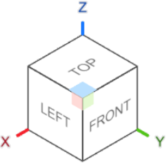
Shortcut Key | Axis | Plane | Visualization (View Cube) |
|---|---|---|---|
Z | Z-axis (up and down) | XZ-plane / Horizontal Work Plane | Blue |
X | X-axis (left and right) | YZ-plane | Red |
C | Y-axis (front and back) | XY-plane | Green |
Click here for visualization.
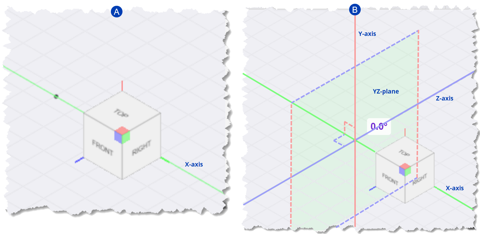
 : The X-axis is visualized as the green line running left and right.
 : When you press X or the Spacebar while locked to the X-axis, you switch to the YZ-plane. The YZ-plane is formed by the Y- and Z-axes which are both perpendicular to the X-axis.
To toggle between the selected axis and its corresponding plane, press the same shortcut key again, or press the Spacebar.
Pressing a different shortcut key switches to that key's corresponding axis or plane, whichever was last active. For example, if you're drawing in the XZ-plane then you press the X key, the active plane will switch to the YZ-plane.
Draw and connect segments
Click on the location where you’d like to place the first waypoint.
By default, the first waypoint snaps to the Work Plane.
Pressing a shortcut key before placing the waypoint will switch to a different drawing plane, though it will remain oriented to the Work Plane elevation.
Click on another location to draw a segment starting from the first waypoint.
PRO TIP:
Drawing while locked to an axis allows you to draw straight along that axis.
Switching to the axis' corresponding plane allows you to draw segments along the axes that define the plane.
Including segments that form standard conduit bend angles from the selected waypoint.
Continue placing waypoints to draw multiple connected segments.
Switch to either Plan or 3D view at any time using the View selector while still in Draw mode.
Toggle between different axis/plane at any time while drawing segments by pressing the corresponding shortcut keys.
Use the navigation controls to move through the model while in Draw mode.
Press Esc or Enter when finished.
Repeat the steps on this section to draw as many segments as necessary to connect the routes for all of the raceways in your floor.
Segments must intersect at shared waypoints to be connected.
Connect a Source/Destination to segments
 Raceways connect to Sources and Destinations through their Surface Connector Targets, which are the purple arrows protruding from some sides. The Targets are attached to the element’s ACP Surface Connectors which are visualized as yellow rectangles.
Follow the steps below to connect a Source/Destination to segments.
Hover your cursor over the element’s Surface Connector Target.
When the Target is highlighted, left-click on it to place a waypoint on the Target.
Move along the axis then click where you’d like to place the second waypoint to create the segment.
A purple rectangle will appear when you reach the Work Plane.
Repeat the steps to connect the other Sources and Destinations.
Once the raceway’s Source and Destination connects with each other:
The raceway’s status in the Conduit Schedule will change to Routed
.png) .
.In the 3D Model Viewer, the segments are assigned to the raceway route, and their Rack Preview is displayed.
.png)
The Rack Preview visualizes the estimated space required for the rack, and automatically adjusts as routes are connected to or removed from the Assigned Segment.
You can
 lock the Height and Width of the Rack Preview from the
  Info pane of the selected segment so its dimensions are no longer adjusted automatically. When locked, the corresponding sides are highlighted in purple.
The
 line in the middle of the segment indicates the orientation of the rack. You can rotate this by clicking the
  Rotate button in the Info pane.
Follow the steps below.
In the Notes column of your Conduit Schedule, indicate the floor where each raceway is placed.
Raceways on the same floor must have the same notes.
In the Search bar at the top, enter the floor you’re currently drawing routes for.
This filters the Conduit Schedule to show only the raceways on the entered floor.
Accept Proposed Routes
By default, the Proposed Segment category (appears as broken lines in the 3D Model Viewer) in the View Controls is set to Visible ![]() . The Proposed Segments in the viewer make up Proposed Routes which connect the Sources and Destinations together into routes based on the shortest distances of all enabled raceways in the Conduit Schedule. Proposed Routes adjust as segments are drawn in the site.
. The Proposed Segments in the viewer make up Proposed Routes which connect the Sources and Destinations together into routes based on the shortest distances of all enabled raceways in the Conduit Schedule. Proposed Routes adjust as segments are drawn in the site.
Proposed Routes may be accepted from the Conduit Schedule to create Entire Raceway Routes. You can also accept a Single Proposed Segment only in the Model Viewer to create Committed Segments.
Because Proposed Routes don’t consider obstructions, supportability, or other real-world construction principles, modification may be required once they are accepted.
Because Proposed Routes are recalculated each time a segment is drawn in the model, they become helpful guides as you manually draw segments.
After you’ve drawn the main racks, the Proposed Routes often show the shortest route to connect a Source and Destination together through those racks. You can then accept the Proposed Routes, or draw more segments to further specify the route you’d like to take.
.png) Proposed Routes are made up of temporary segments in the 3D Model Viewer. To accept a Proposed Route for a raceway, each segment in the route must be individually accepted.
Proposed Routes are made up of temporary segments in the 3D Model Viewer. To accept a Proposed Route for a raceway, each segment in the route must be individually accepted.
Follow the steps below.
Switch to Select mode.
If you’re in Draw or Move mode, press the Esc key until neither is selected in the
 Mode Selector.
Hover over any
 Proposed Segment in the 3D Model Viewer.
Once highlighted, double-click to accept the segment and create a Committed Segment.
Repeat to accept other Proposed Segments in the Viewer.
Once you’ve accepted all the Proposed Segments making up a Proposed Route, the raceway’s status in the Conduit Schedule will change to Routed and the accepted segments become Assigned Segments with the Rack Preview.
View Controls button then disable the
Section Cut toggle for the Proposed Segment category group.
.png) ACP displays Proposed Routes only for enabled raceways in the Conduit Schedule. When you accept a Proposed Route in the Conduit Schedule, all of the segments making up that route are accepted.
ACP displays Proposed Routes only for enabled raceways in the Conduit Schedule. When you accept a Proposed Route in the Conduit Schedule, all of the segments making up that route are accepted.
Follow the steps below to accept a Proposed Route(s).
In the Conduit Schedule, ensure that the
 Active toggle for the raceway is enabled.
The status of the raceway will change to Proposed Route
.png) or No route found
or No route found .png) .
.
Click the raceway’s
 Proposed Route status to accept it.
To accept all Proposed Routes, click the
 Status header.
Turn off Proposed Routes
The Proposed Route calculations may be turned off from the Menu button located in the
Click the Menu
 button.
 Uncheck the Proposed Routes checkbox.

Adjust the drawing orientation
By default, the Model Viewer and drawing orientation are aligned to the Revit Project North. This works well for most buildings, but real projects frequently include areas that break away from that alignment.
While drawing routes, the orientation of the Segments, Proposed Routes, and the View Cube may be rotated to account for odd angles and off-axis areas of the building.
 Follow the steps below to set the drawing orientation:
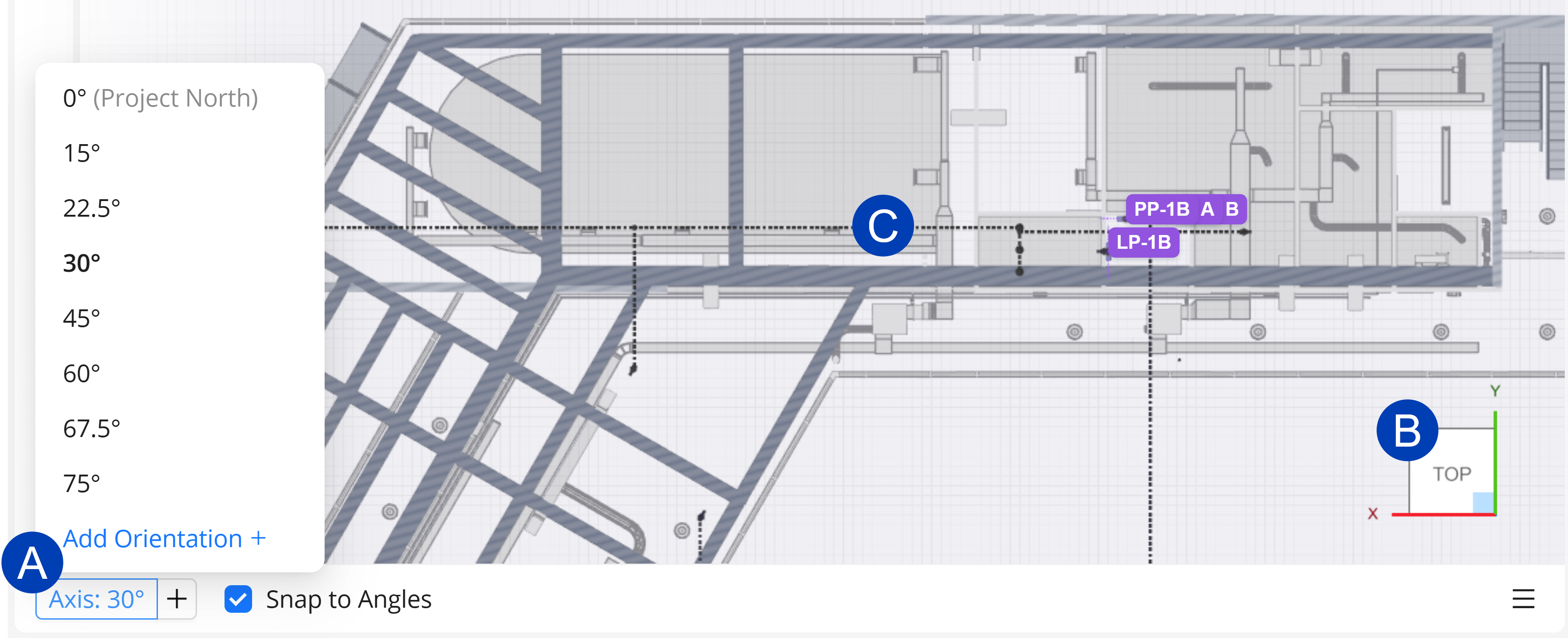
Click the (A)Axis Orientation dropdown in the status bar.
Select a standard bend angle from the list, or click Add Orientation + to enter a custom angle.
The selected angle becomes the new orthogonal X/Y orientation, and
the (B)View Cube updates to match.(C)Proposed Routes will also update to reflect the new orientation.
Draw your segments in the off-axis area.
When finished in the off-axis area, return to 0° (Project North) to resume standard drawing.
Disable Angle Snapping 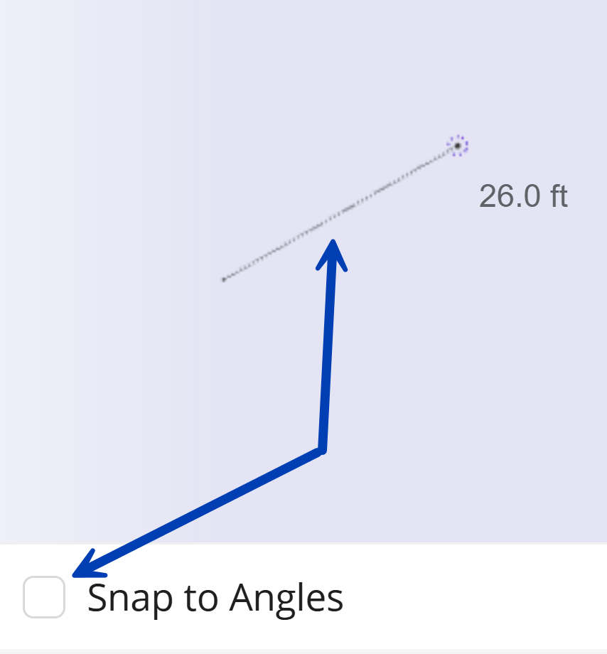
Sometimes standard bend angles cannot fully account for the direction a straight run of conduit needs to travel.
This is especially true for underground routing, where connecting a Source and Destination as the crow flies is often the most practical approach.
To draw segments at any angle:
Uncheck Snap to Angles
 in the status bar.
 When finished, re-enable it to resume orthogonal snapping, with Shift available for standard bend angles.
Next Steps
Segments in the model may be edited at any time. Refer to the next article, Editing Segments.