Many factors influence how ACP routes conduit between a Source and Destination. Some of these factors come from Revit (such as category and part type), while others are introduced by ACP (such as Enabled status and ACP Surface Connectors).
This article outlines these variables and explains how each one affects the specific kinds of electrical elements within an ACP Project.
Revit categories
The element categories which may be used as a Source and Destination for each Raceway are Electrical Equipment and Electrical Fixtures.
Typically used to represent items such as panels, transformers, and other primary electrical equipment.
These elements are identified using the Panel Name parameter.
Represents electrical components, including end-point devices such as junction boxes and receptacles, as well as access-point devices such as pull boxes.
These fixtures require unique identifiers through the ACP_E_Fixture_ID parameter for identification within ACP.
This is because they have no default parameter for identification.
Element identification
The parameters in the table below are used to identify Electrical Equipment and Electrical Fixtures in the Revit project for use in the ACP workflow.
Parameter | Applied Revit Category | Description |
|---|---|---|
ACP_E_Fixture_ID | Electrical Fixture | A shared project parameter added to the Revit project during Initialization. This is used to identify electrical fixtures for use in the ACP workflow. |
Panel Name | Electrical Equipment | A Revit-native parameter which exists in every Revit project. This is used by most electrical teams to identify each unique piece of electrical equipment. ACP uses this parameter similarly for its workflow. |
ACP_C_Enabled | Electrical Equipment Electrical Fixtures | A shared project parameter added to the Revit project during Initialization. If this parameter is set to Yes, the electrical elements will be included as part of the Electrical Model for ACP. |
Excluded Geometry
Clearance Subcategory.png)
Electrical Equipment and Electrical Fixtures are often modeled with additional geometry to represent required clearances, which prevent other trades from routing content through those areas. However, this clearance geometry can interfere with ACP’s ability to route conduit to the equipment.
To support accurate conduit routing, any geometry assigned to a Subcategory of either of these categories, containing the word Clearance in its name, is automatically excluded during ACP Import.
Because this adjustment only affects the ACP import, it has no impact on the Revit model itself or on coordination with other trades.
Fine Detail Level
Electrical Elements such as Electrical Equipment and Electrical Fixtures, are imported into ACP at the detail level of Medium, to allow for accurate detection of connectors, and avoid importing small internal components that could interfere with routing.
Any geometry set only to the Detail level of Fine will automatically be excluded from the Electrical Model in ACP.
Element Connectors
There are two types of connectors used in the ACP conduit routing process: Revit Electrical Connectors and ACP Surface Connectors. Each is a distinct kind of element with its own function.
Revit Electrical Connectors .png)
Any Revit family with an element intended to be a Source or Destination must have at least one Electrical Connector.
Revit Native elements added into loadable families within the family editor.
.png)
Requirements:
Electrical Equipment - The Revit Electrical Connector element is NOT required for Electrical Equipment to be a Source or Destination for ACP.
Electrical Fixtures - The location of the Revit Electrical Connector establishes the “Back Face” of the fixture. This controls which faces of the Electrical Fixture that may have conduit routed to it.
See the Electrical Fixtures section of this article for additional information on how this works.

ERROR: Electrical Connector missing in Electrical Fixture family instance
When importing the Electrical Model, you will will encounter this error if any enabled electrical element does not contain an Electrical Connector.
Click here for steps to clear this error
From the error details, copy the Revit Element ID flagged by ACP.
In your Revit project, locate the element using the copied ID.
Do either of the following to resolve the error:
Add a Revit-native Electrical Connector to the element’s family
Replace it with an element belonging to a family which already includes a valid Electrical Connector.
After ensuring that the connector is correctly placed, re-import the Electrical Model.
Note: The electrical model is not successfully imported until the timestamp is present under the Import Active Revit Project button as shown.
ACP Surface Connectors - General Rules
ACP generates Surface Connectors for each enabled electrical element, based on the faces eligible for conduit routing.
Determined by the element’s category and part type.
Visualized only in the ACP 3D viewers and are never added to or visible within the Revit project.
For more details on how surface connectors are placed for different elements, refer to the category and part type information in the Electrical Equipment and Electrical Fixture sections below.
, which is typically used to connect elements within the Revit conduit system. These Revit Native Conduit Connectors are not required within the manual conduit modeling workflow, and often introduce complications with conduit routing and element placement when used. As such, ACP does not utilize them to connect a source or destination into the Conduit Run, and Revit Conduit Connectors are not required on any electrical elements used as a source or destination in ACP.
If they are present, ACP will ignore them during conduit routing.
Clash-Free boxes - General Rules
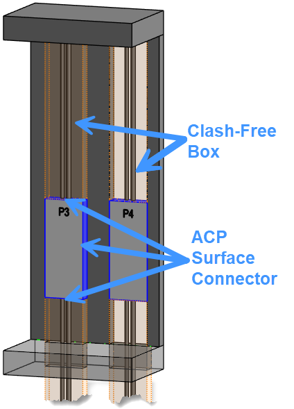
Image is a reference only.
Clash-Free Boxes are not visualized
in Revit or in the ACP Viewer.
In order to create an easier Revit project setup process, ACP automatically applies a Clash-free Box to some enabled Electrical Equipment (based on part type), and all enabled Electrical Fixtures (based on connector location).
These boxes allow ACP conduit to penetrate through obstructions around the Source and Destination.
Below are key characteristics of Clash-Free boxes and the general rules they follow during routing:
They are only ever applied to surfaces that have ACP Surface Connectors and are considered Routable.
Not all surface connectors will have Clash-Free boxes applied to them.
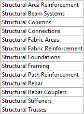 To maintain realistic routing, any Revit category with Structural in its name is excluded from these clash-free penetrations and stops the Clash-Free Box.
 This prevents conduit from being routed through beams, columns, or other structural components when exiting a panel.
They are never visualized in Revit OR the ACP Viewer, but are respected during routings.
This means you won’t see the boxes themselves, only their impact on how conduit is routed.
For more details on how clash-free boxes are placed for different elements, refer to the category and part type information in the Electrical Equipment and Electrical Fixture sections below.
ACP_E_Target_Bottom_Face
In Revit models, underground areas are not reliably recognized as underground or occupied. Because they have few or no obstructions, ACP favors them and treats these regions as if they are available for routing. A Source or Destination with a Clash-Free box placed on the ground floor allows conduit to penetrate the floor slab above. Once ACP enters these areas, it routes underground as if it were overhead, ignoring proper underground conduit rules.
To control routing at the bottom of the Source/Destination, you can use the ACP_E_Target_Botton_Face parameter added to the Electrical Equipment in your Revit project during Initialization.
When unchecked, this parameter disables the Clash-Free Box on the bottom face and prevents any bottom-face connections.
.png)
Disabling the ACP_E_Target_Bottom_Face property ensures that conduit is not routed through the floor slab and ultimately underground unless explicitly intended.
Electrical Equipment breakdown
Electrical Equipment such as Panelboards, Transformers, and Switchboards each have specific rules for how and where conduit may be connected. To handle these differences, ACP references the Part Type parameter within the Electrical Equipment family. This parameter allows ACP to distinguish between different types of equipment and apply appropriate routing logic. Each part type is treated differently during the conduit routing analysis to reflect its unique connection requirements.
Panelboard & Other panels
For Panelboards and other panels, conduit connections may be made to the top, bottom, or sides of the panel.
Here’s how ACP configures these for routing:
ACP Surface Connectors are applied to the top, bottom, and two sides of the Panel.
A Clash-Free Box is applied to both the top and bottom faces of the Panelboard, extending a minimum of 6’ in each direction. The behavior of the Clash-Free Box and conduit will vary depending on the surrounding Structural and Non-Structural elements.
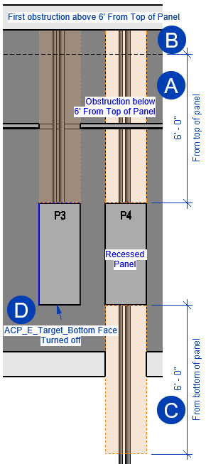 Top Clash-Free Box
The top Clash-Free Box may extend further than 6’ and allows two different behaviors:
 Within 6’ above the panelboard, the Clash-Free Box penetrates any non-structural obstruction.
The Clash-Free Box may also not penetrate Floor or Roof structures above the panel.
 Past 6’ above the panelboard, the clash-free box continues to extend but only allows conduit to run within walls. When another obstruction is encountered, the clash-free box will end.
This behavior is designed to allow conduit to reach the top of a recessed panel from any raceway height, provided there are no obstructions.
Bottom Clash-Free Box
 The bottom Clash-Free Box only extends 6’ below the panelboard and penetrates any non-structural elements within.
 If the ACP_E_Target_Bottom_Face property is unchecked, there will be no bottom Clash-Free Box because the bottom face will be considered Not Routable and no ACP Surface Connector will be generated for that face.
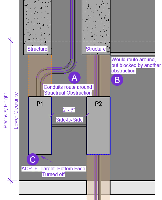 Clash-Free Boxes don’t penetrate Structural elements at all. Instead, conduit will route around the structural obstruction.
ACP doesn’t route horizontally within the Raceway Height’s Lower Clearance but, to
 route around a structural obstruction blocking the clash-free box of a source or destination in this area, ACP will insert a horizontal segment up to 1 foot and 6 inches in length. The conduit will then continue vertically to connect to the conduit rack or run horizontally at the set Preferred Height.
 If there’s another obstruction in the path that the conduit takes to route around the structural obstruction, routing will be blocked.
 If the ACP_E_Target_Bottom_Face property is unchecked, there will be no bottom Clash-Free Box because the bottom face will be considered Not Routable and no ACP Surface Connector will be generated for that face.
Side-to-Side connections
 Panelboards installed next to each other are typically connected in the field using a short side-to-side conduit(s), commonly referred to as a nipple. ACP is designed to recognize these panelboard placements and automatically create a connection, rather than routing conduit from the tops of the panels.
ACP determines if panels are side-by-side by first looking at the Space information in the Revit project, when no spaces are present in the Revit project, additional considerations are evaluated.
With Spaces | No Spaces |
|---|---|
When spaces are modeled ACP identifies the boundaries of each space and ensures that side-to-side connections are only made between panelboards within the same space. | When no spaces are present: ACP identifies and creates a side-to-side connection between panelboards located. within 30 feet of each other. However, without space data, ACP cannot verify whether the panelboards are in the same room. As a result, it may create a side-to-side connection through a wall if the panelboards appear close in the model but are actually separated by a partition. |
The Lower Clearance constraint within the Raceway Height Design Rule ensures that all horizontal conduits maintain a minimum elevation above the finished floor, with a couple of exceptions:
When routing around structure to get to a Source or Destination below the Lower Clearance.
When connecting two Side-to-Side panels which are within 2’-6” of each other.
If the Raceway Height is set at or above the top of the panelboards, and the panels are more than 2’-6” apart, ACP will be unable to create a horizontal connection between them.
The raceways to these panels may either be excluded from the study using the Active setting in the Conduit Schedule, or a work around may be applied to the electrical rooms.
Click here for Electrical Room workaround
Create a Scope for the Electrical Rooms.
Use spaces (if present) and the ACP_Area_Class parameter to group Electrical Rooms into a shared Scope.
If no spaces are present, use named scope boxes to define Electrical Room volumes.
Create a separate Design Rule Constraint for each scope
Assign each scope to its corresponding Design Rule Constraint.
Set the Design Rule Constraint height lower than the top of the panels (e.g., 4 ft) to enable side-to-side connections.
See the article Assigning a Design Rule to a Scope for more information.
Switchboard
Image is a reference only.
Clash-Free Boxes are not visualized
in Revit or in the ACP Viewer.
For Switchboards, conduit connections may be made to the top, bottom, and sides of the panel.
Here’s how ACP configures Switchboards for routing:
ACP Surface Connectors are only applied to the top and bottom of the Switchboard.
Clash-Free box is applied to the top and bottom faces of the Switchboard, extending 6’ out in each direction.
A Clash-Free Box is applied to both the top and bottom faces of the Panelboard, extending a minimum of 6’ in each direction.
If the Clash-Free Box encounters Structural elements, it will stop. Conduit will then route around the structural obstruction.
If the source or destination is below the Raceway Height Lower Clearance, ACP will insert a horizontal conduit segment up to 1 foot 6 inches in length, then continue vertically to connect to the conduit rack.
The top Clash-Free Box will penetrate any elements not in the Structural, Floor, or Roof categories until it reaches 6 feet above the panelboard.
Once 6 feet is reached, it will continue extending until it encounters an obstruction such as ductwork, ceiling, or mechanical equipment.
The bottom Clash-Free Box will penetrate any Non-Structural elements until it reaches 6 feet below the panelboard, then stop.
When the ACP_E_Target_Bottom_Face property is unchecked, the bottom face will be considered Not Routable, and the ACP Surface Connector for that face will not be generated.
No Side-to-Side connections allowed
This means their connections will not be impacted by the Raceway Height design rule.
Switchboard Sections
ACP looks for and identifies individual elements in order to route conduit between each Source and Destination. Switchboards are often modeled as one single element containing multiple sections of that gear. In order for the conduit to correctly terminate at each section you will need to provide a family instance for each section of the gear, and identify each with a unique name in the Panel Name property.
PRO TIP:
ACP can identify individual shared families nested within a main family. This allows you to use a shared family to simulate a conduit window for each section of equipment within a single family, and ACP will recognize and route to those instances.
Click to see conditions
The nested family instances are set to Shared within the family parameters.
Shared families are treated as individual elements in the project, allowing them to be scheduled and assigned properties independently from the host family.
They belong to the categories ACP supports (IE: Electrical Equipment or Electrical Fixtures)
Each instance is manually selected within the Revit project and enabled using the ACP_C_Enabled parameter.
Each instance is manually selected within the Revit project and given a unique name using the Panel Name parameter.
It’s up to you to decide whether this approach is more efficient than modeling each section as a separate family instance.
Transformer.png)
Unlike other equipment, conduit does not terminate directly on any face of the transformer. Instead, conduit is routed to terminate near the transformer and then connected using flex conduit (also known as a whip).
Here’s how ACP configures Transformers for routing:
ACP Surface Connectors are created within an offset of 12 inches from the sides of the Transformer.
Conduits can then terminate:
Straight into the top or bottom of these ACP Surface Connectors
Or with a 90° turn into the side or back connectors.
No Clash-Free box
Because conduit does not terminate directly on the equipment face, ACP does not Generate a Clash-Free Box on transformers.
The bottom connector can terminate conduit near a transformer’s base, but not when the transformer sits on a building pad, even with ACP_E_Target_Bottom_Face enabled.
To access the bottom connector as a termination point, the transformer must either be suspended in the air or a May Route Box must be used.
Side-to-Side connections
Transformers installed near panelboards are typically connected in the field using a short side-to-side conduit(s), commonly referred to as a nipple. ACP is designed to recognize these Panelboard/Transformer placements and automatically create a connection, rather than routing conduit from the tops of the panels.
ACP determines if panels are side-by-side by first looking at the Space information in the Revit project, when no spaces are present in the Revit project, additional considerations are evaluated.
With Spaces | No Spaces |
|---|---|
When spaces are modeled ACP identifies the boundaries of each space and ensures that side-to-side connections are only made between panelboards within the same space. | When no spaces are present: ACP identifies and creates a side-to-side connection between panelboards located. within 30 feet of each other. However, without space data, ACP cannot verify whether the panelboards are in the same room. As a result, it may create a side-to-side connection through a wall if the panelboards appear close in the model but are actually separated by a partition. |
The Lower Clearance constraint within the Raceway Height Design Rule ensures that all horizontal conduits maintain a minimum elevation above the finished floor, with a couple of exceptions:
When routing around structure to get to a Source or Destination below the Lower Clearance.
When connecting two Side to Side panels which are within 2’-6” of each other.
If the Raceway Height is set at or above the top of the panelboards, and the panels are more than 2’-6” apart, ACP will be unable to create a horizontal connection between them.
The raceways to these panels may either be excluded from the study using the Active setting in the Conduit Schedule, or a work around may be applied to the electrical rooms.
Click here for Electrical Room workaround
Create a Scope for the Electrical Rooms.
Use spaces (if present) and the ACP_Area_Class parameter to group Electrical Rooms into a shared Scope.
If no spaces are present, use named scope boxes to define Electrical Room volumes.
Create a separate Design Rule Constraint for each scope
Assign each scope to its corresponding Design Rule Constraint.
Set the Design Rule Constraint height lower than the top of the panels (e.g., 4 ft) to enable side-to-side connections.
See the article Assigning a Design Rule to a Scope for more information.
Equipment Switch (Not Supported)
Because the Revit part type Equipment Switch does not include the default Panel Name parameter, it is not supported in the ACP workflow. To ensure conduit can be modeled to these devices, use the Other Panel part type for disconnects and similar switches.
Electrical Fixtures breakdown
The Electrical Fixtures category is typically used in Revit to represent access-point devices such as pull boxes, and end-point devices within the electrical systems such as junction boxes, receptacles, and other devices.
This also applies in the ACP workflow, where it’s most commonly used to represent a junction box (either a Home Run box or a larger pull box). These boxes have strict rules about which faces can connect to conduit. To accommodate this, ACP lets you control the assigned faces of the junction box based on the location of the Revit Electrical Connector.
.png) ACP Surface Connectors are applied based on the Revit Electrical Connector location.
ACP Surface Connectors are applied based on the Revit Electrical Connector location.The face where the Revit Electrical Connector is placed is the Back Face of the box once placed in the project. The opposite face then becomes the Front Face, and each adjacent face is considered a Side Face.
The Back Face, and each Side Face are considered routable. ACP will apply ACP Surface Connectors to these faces.
.png)
Clash-Free boxes are also applied based on the Revit Electrical Connector location.
ACP applies a Clash-Free Box, which extends 12” out on each side, to each of face of the Electrical Fixture considered Routable (See above).
This prevents conduit routes to junction boxes accidently placed within other geometry (IE: Ducts, pipes, equipment, etc.) from failing to route.
.png)
PRO TIP:
ACP can route conduit to penetrate walls perpendicularly but will not route conduit within a wall. As a result, recessed electrical fixture elements (for example, end-device receptacles) will fail to route because their clash-free boxes do not extend far enough up the wall to reach the horizontal conduit rack above.
To enable routing to recessed Electrical Fixtures, place a May-Route box in the wall, starting at the fixture’s top face and extending up to the horizontal rack height. This gives ACP a clear routable path inside the wall.
.png)