In Revit, Spaces are used in MEP workflows to store MEP-specific data for regions within a building, unlike architectural Rooms. With native Revit features, you can transfer Room data, such as Room Name and Room Number, into the spaces for easier control and use within the project.
ACP leverages this feature for the following key functions:
Guidance Spaces: Defines Preferred Spaces and Keep Out Spaces for conduit routing.
Assigning Scopes to Design Rules: Enables granular control of projects to control routing preferences.
Can be assigned by Space Name, or by Area Classification.
This guide explains how to set up and assign spaces in Revit for optimal use within ACP. The following steps are completed using Revit’s native functions.
Using Spaces is not technically required by ACP, so it’s possible to process a Revit project without any Spaces in it. However, it’s highly recommended to properly configure Spaces in your Revit project so you can use the additional functionality of “Preferred Routing”, and “Scoping Design rules”.
Set up Revit Spaces for ACP
Enable Room Bounding in linked files .png)
Spaces in Revit depend on bounding elements (such as walls, floors, and ceilings) to define their shape and volume. While the settings for these bounding elements are ultimately set within the linked models (often the Architectural Model), you must specify which links should be used as Room Bounding to define the spaces.
.png) Follow the steps below.
Follow the steps below.
In the Project Browser, select the linked model.
Navigate to the Properties panel.
Select Edit Type.
In the Type Properties window, check Room Bounding on.
Place spaces in the Revit project
To Import spaces with the Electrical Model in ACP, they must be created in Revit Floor Plan views. Spaces attach to the view’s Associated Level and aren’t visible in 3D views, so this process must be repeated for each project level.
Follow the steps below.
Navigate to the Analyze tab.
.png)
Within the Spaces & Zones panel, click the Space
.png) tool.
tool. Ensure that Tag on Placement
.png) is Highlighted blue (indicating that it is active).
is Highlighted blue (indicating that it is active).This will place a tag within the Space upon creating it, saving you a step.
Select Place Spaces Automatically
.png) .
.
Space Tags are a separate element from the Spaces themselves (just like with all tags). This means that spaces may exist in a floor plan without the Space Name and Number being shown.
If your floor plan is not displaying the Space Tags, they may be easily placed by using the Tag All tool
found in the Tag Panel, within the Annotate tab.
Once the Tag All Not Tagged window is open, scroll down the list of the loaded tag categories
Check the box next to
Space Tags
Select the
Loaded Tags to place for the selected category (in this case Space Tags).
Click
OK to place the specified tag at each instance of the tag category (in this case Spaces).
Name spaces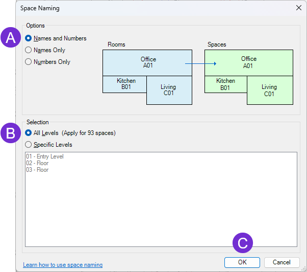
Revit Spaces can reference Room Names and Room Numbers.
The Space Naming tool allows for the transfer of that data directly onto the space so that the space names and numbers match the room names and numbers.
Follow the steps below.
In the ribbon, navigate to the Analyze tab and select the Space Naming tool
.png) within the Spaces & Zones panel.
within the Spaces & Zones panel. Select
 Names & Numbers (Recommended) under Options.
Select either All Levels, or choose specific levels under
 Selection
Click
 OK to confirm your settings and close out the window.
The names and numbers in the space tags should now match your room names and numbers.
Clean out unneeded spaces .png)
Revit does not use existing rooms to create spaces. Instead, it relies on bounding elements (walls, ceilings, etc.) from the linked model. As a result, some spaces may be created in areas with no corresponding rooms.
To remove these excess spaces (such as those in plumbing chases or wall wraps), follow the steps below:
After completing the Space Naming workflow, create a Revit schedule for the category Spaces.
Select and delete
.png) the unneeded spaces from the schedule.
the unneeded spaces from the schedule. These spaces are typically still named Space, even after the Space Naming workflow is implemented.
Deleting a space from the schedule will also delete it from the project.
When the Electrical Model is imported into ACP, the Upper Limit of each space is automatically set to the next level above. ACP then uses this Upper Limit to calculate the full volume of the space, rather than relying on bounding elements such as ceilings or floors. This ensures that ACP can accurately utilize the complete space volume for Guidance and Design Rule Scopes.
Troubleshooting Spaces
Ensure all rooms have properly enclosed spaces
Because Revit relies on "Room Bounding" elements from the architectural model to define space boundaries, issues may occur when elements are not properly set or when geometry from the linked model does not translate cleanly. As a result, some spaces may fail to form correct boundaries.
Since ACP depends on accurately bound spaces, you may encounter the following message when spaces are incomplete or invalid:
The space <space name> produced a mesh with zero faces or verts..png)
If the affected spaces are needed for ACP-specific functions, such as creating a Scope for a Design Rule or assigning Preferred Spaces, you will need to adjust their boundaries using Space Separators within your model. Space Separators ![]() will often help to manually define or correct the boundaries so ACP can recognize and use the spaces correctly.
will often help to manually define or correct the boundaries so ACP can recognize and use the spaces correctly.
Here are some steps you can take to help you identify and ultimately correct the boundaries of the spaces.
Visualize spaces.png)
Spaces are only visible within 2D views (Plan views, Section views, and Elevation views). By default they are completely transparent, and will only be identifiable by the Space Tag, or by hovering over the boundary of the space until the diagonal lines of the space appear (See image). In order to better assess if all architectural rooms have spaces placed in them you can visualize the spaces in two ways:
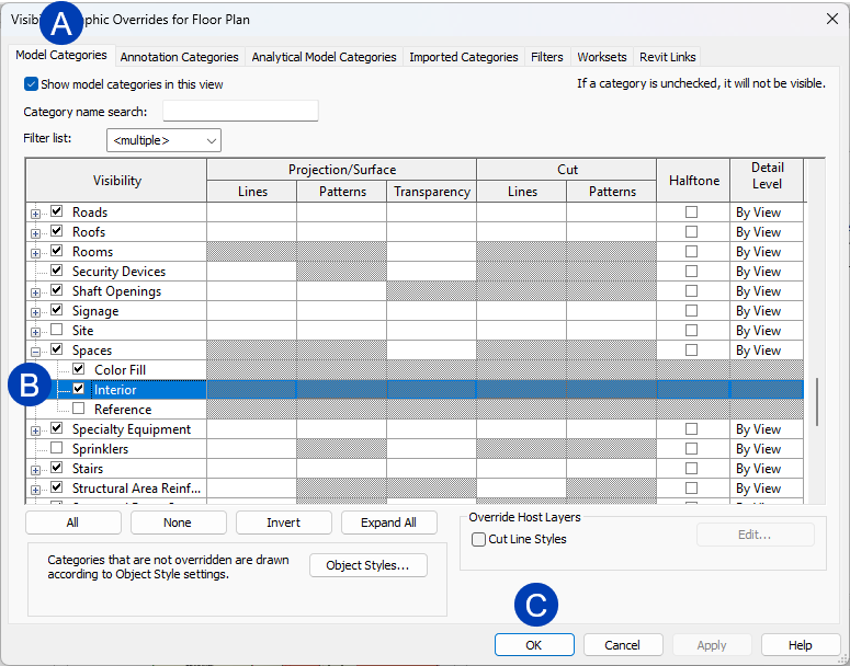 Turn on the interior space shading in the Visibility/Graphic Overrides (See Image).
Open the Visibility/Graphic Overrides window for your 2D view.
You will need to make these adjustments directly in the View Template if one is applied.
In the
 Model Categories tab, locate the category of Spaces.
 Expand the category to show the Spaces sub-category list
Check the box for
 Interior to turn on the interior fill of the view.
 Click
 OK to apply the change and close the Visibility/Graphic Overrides window.
Assign a space color scheme to the view.
Select the Color Scheme property
.png) from the Properties Pallet.
from the Properties Pallet. This will open the Edit Color Scheme window.
.png) Select
Select .png) Spaces from the Category dropdown list.
Spaces from the Category dropdown list. Select or create a new color scheme which will create shading in all existing spaces.
Typically using one where the color is assigned based on the
.png) Name of the space does a good job of visualizing the various spaces and relationships between them.
Name of the space does a good job of visualizing the various spaces and relationships between them.
Click OK to finalize your selection and apply it to the view.
The ACP-Plan view template (created during initialization) turns on the Interior fill for spaces, and overrides the color to a neutral gray for easier identification of Preferred and Keepout Spaces.
Turn on Room fill
In some cases, architects may choose not to place a room within enclosed areas (such as plumbing chases, elevator shafts, specific corridors, or open spaces). Making room interior fills visible can help you identify which regions contain rooms and highlight areas where boundaries might be missing or incorrect in your model
The process for making rooms visible is similar to making the Space Interior fill visible for spaces: .png)
Open the Visibility/Graphic Overrides window for your 2D view.
In the Model Categories tab, locate the category of Rooms.
Expand the category to show the Rooms sub-category list
Check the box for Interior Fill to turn on the interior fill of the view.
Click OK to apply the change and close the Visibility/Graphic Overrides window.
All spaces successfully placed within a room will appear with a slightly bluer hue, while all rooms that are not correctly enclosed as spaces will appear as a light blue color. (See Image)
Correct the Space boundary.png)
Once your spaces and rooms are visibly colored within your floor plan, it becomes easier to identify areas where rooms exist, but where Spaces haven’t been successfully enclosed. While there isn’t a foolproof method for resolving these issues, in some cases, adjusting a specific boundary segment with a space separator may be enough.
If that step is unsuccessful, the following steps are often effective:
Create a new Space Boundary.
Use Space Separators
.png) to define boundaries manually with draw tools.
to define boundaries manually with draw tools.If Rooms are visible, the Pick Line
.png) tool may be used to easily create the boundary line based on the existing edge of the room, without needing to manually trace it.
tool may be used to easily create the boundary line based on the existing edge of the room, without needing to manually trace it. Sometimes the Pick Line tool does not grab the entire length of a side and will not automatically create a closed boundary for the space.
It will be easiest to create only one segment per side, and then use the Trim/Extend to Corner
.png) tool to create a fully enclosed boundary for the space.
tool to create a fully enclosed boundary for the space.
Ensure a Space is placed within the new Space boundary.
Sometimes when you repair the boundary the existing space will reappear in the view. While this is the ideal, it is not always the result. If this doesn’t happen, a new space may be placed within the boundary.
Within the Spaces & Zones panel, click the Space
tool. Ensure that Tag on Placement
is highlighted blue (indicating that it is active).This will place a tag within the Space upon creation, saving you a step.
Manually place the space within the newly created boundary.
Do not use “Place Spaces Automatically”
Use the Space Naming tool
.png) to transfer the Room Names and Numbers to the new Space.
to transfer the Room Names and Numbers to the new Space. .png)
Clean out any duplicate spaces .
If the existing problematic space is still in the model, Revit will give you the warning: “Elements have duplicate “Number” values.”, after using the Place Spaces Automatically. Here’s how to resolve this:
Navigate to an existing Space schedule, or create a new one
Ensure the schedule is sorted by “Name”.
When the Space Naming tool is run and duplicate spaces are identified, Revit will add a “-1” and “-2” to each of the duplicate spaces.
Select the row for the “-1” duplicate (This is most likely the problematic Space).
Click the Delete button from the Modify Schedule/Quantities tab.
This will delete the extra space from the entire project.
Verify the correct space remains within the plan view.
Rerun the Space Naming tool to correct the Space Name and Number.
Double-check the Section Box boundary.
ACP utilizes the ACP-Import 3D view’s Section Box to identify which elements are part of the Electrical Model to be imported into ACP. If the Section Box cuts into (or clips), an element in the ACP-Import 3D view, that element will not be imported into ACP.