The 3D view named ACP-Import (created during project initialization) in the Revit project determines which elements are imported into the ACP Study as part of the Design Inputs.
Because the ACP-Import view is where ACP pulls all of the Revit data, if the add-in detects that this view is missing, you will be prompted to initialize the project again when trying to use any of the add-in tools. Or the project will be automatically reinitialized when importing either the Electrical Model or Background Geometry into the study.
This article provides guidance on how to set up the ACP-Import view to specify the geometry which should be imported into the ACP study.
Design Inputs
In an ACP study, the Design Inputs serve as one of the bases for routing, collision avoidance, and Solution generation. It includes the Electrical model and Background geometry.
When setting up the ACP-Import view, consider that the following must be imported into the ACP study:
Electrical model
Identifies the location, size, and other properties of the enabled Electrical Equipment and Electrical Fixtures which ACP will use as sources and/or destinations for the conduit routing, as well as various elements used for constraining routes.
The elements imported with the Electrical model are:
All enabled Electrical Equipment and Electrical Fixtures
Guidance Boxes and Guidance Spaces
Scoping elements
Spaces (Including Area Class and Preferred Space data)
Scope Boxes
 Existing conduit runs in the Revit project are imported as part of the Background geometry.
Background geometry
Includes all elements in your Revit model (linked or otherwise) which aren’t imported into ACP as part of the Electrical Model. It provides ACP with critical spatial context, including available space for conduit racks as well as obstructions such as walls, beams, and other trade elements. It also identifies supportable elements in the model, enabling ACP to generate conduit racks which are both clash-free and properly supported.
Includes elements used for collision avoidance and path planning in the main model and across different linked models such as architectural, structural, and other trades.
Controlling importable geometry
ACP only imports model elements which are both visible in the ACP-Import view and is fully-enclosed within the ACP-Import view’s section box at the time the Design Inputs are imported into the study. Because of this, managing visibility settings and section box boundaries in the ACP-Import view is critical to creating clean, accurate imports and preventing unneeded geometry from being imported, or essential geometry from being missed.
The following sections explain how ACP evaluates your Revit project for importable geometry.
Using visibility settings
ACP imports geometry from the ACP-Import view in your Revit project based on the applied visibility settings. It follows most of Revit’s standard controls: Category, View Filters, Worksets, Revit Links, Phases, and Design Option.
These visibility settings can be configured either in the view controls of the ACP-Import view or in the ACP-Import-Template, which is automatically applied when the ACP-Import view is created.
Exceptions
While most visibility settings are supported, a few limitations and exceptions apply.
Refer to the table below.
Feature | ACP Behavior |
|---|---|
Subcategories | Ignored. Visibility is inherited from the parent category.
|
Detail Level | All geometry is imported at Fine detail level, regardless of the setting in the ACP-Import view.
|
View Scale | Ignored. Geometry is imported and visualized the same in ACP regardless of setting. |
Visual Style | |
Graphic Display Options | |
Underlay Visibility Override for Revit Links | |
Crop Region | Ignored. Crop regions should only be applied to 2D views. |
Non-physical elements such as:
| Excluded from Import. These elements are intentionally excluded from the import due to their lack of physical geometry. |
Specific Model Categories | Excluded from Import. These elements are intentionally excluded from the import because they cause issues with the building analysis and routing.
|
 Light Sources - Elements within the Light Fixtures subcategory that carry IES data for specific fixtures. They typically create many unique surfaces, which can significantly slow down ACP processing when imported.
PRO TIP: Avoid using the Hide Elements command regularly. Elements hidden using this may be hard to track as your Revit project grows. Instead, manage visibility with Category Overrides, View Filters or Worksets for better control.
Using the View Template
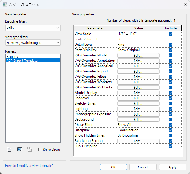 When the ACP-Import view is created, the ACP-Import-Template view template is automatically applied to it. By default, all visibility settings are included in this view template with the suggested configuration commonly used for importing geometry into an ACP study. However, the settings for Worksets and Revit Link overrides (which are project-specific) will likely need to be manually adjusted within the view template.
Model Categories
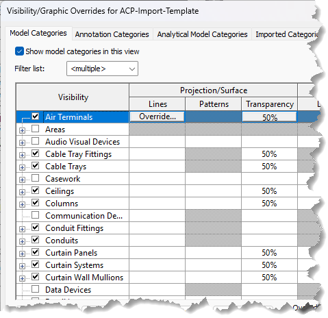 In the ACP-Import-Template, the Visibility has been turned off for some model categories to minimize the amount of geometry imported into the ACP study, allowing for a more efficient process and less time required to Generate solutions.
These model categories have been found to be regularly excluded from the ACP import because they are not considered obstructions which ACP needs to consider in creating routes as they are typically:
Embedded in walls
Lower than typical Raceway height
Not required for clash detection
Using the Section Box
The Section Box in the ACP-Import view limits the model region which gets imported into the ACP study. All elements which are outside of the Section Box will be excluded from the import.
By default, the Section Box expands to the full model extents, encompassing all elements regardless of their location. This can be problematic when linked models contain elements positioned far from the actual building, greatly increasing the overall model extents. ACP analyzes the entire site (including empty space) to determine if it’s occupied or available for routing, these inflated extents force ACP to process a much larger area than necessary. This can significantly slow solution generation and is likely to cause ACP to return an error and fail to generate solutions.
The Section Box may be adjusted to encompass different model regions in two ways: by manual adjustment or by assigning a Scope Box to the view.
.png) Without a Scope Box assigned to the view, the Section Box may be manually moved and resized.
Without a Scope Box assigned to the view, the Section Box may be manually moved and resized.
To move the Section Box, select its boundary then drag to the preferred location.
To resize the Section Box, select its boundary then use the pull points (such as
 ) in each face for adjustment.
in the ACP-Import view by default, but may be disabled if careful attention is not taken. Ensure that the Section Box is enabled and/or a Scope Box is assigned to the view.
Scope Boxes may be created for different model regions and alternately assigned to the ACP-Import view to process each one separately.
Follow the steps below to create a Scope Box and assign it to the ACP-Import view.
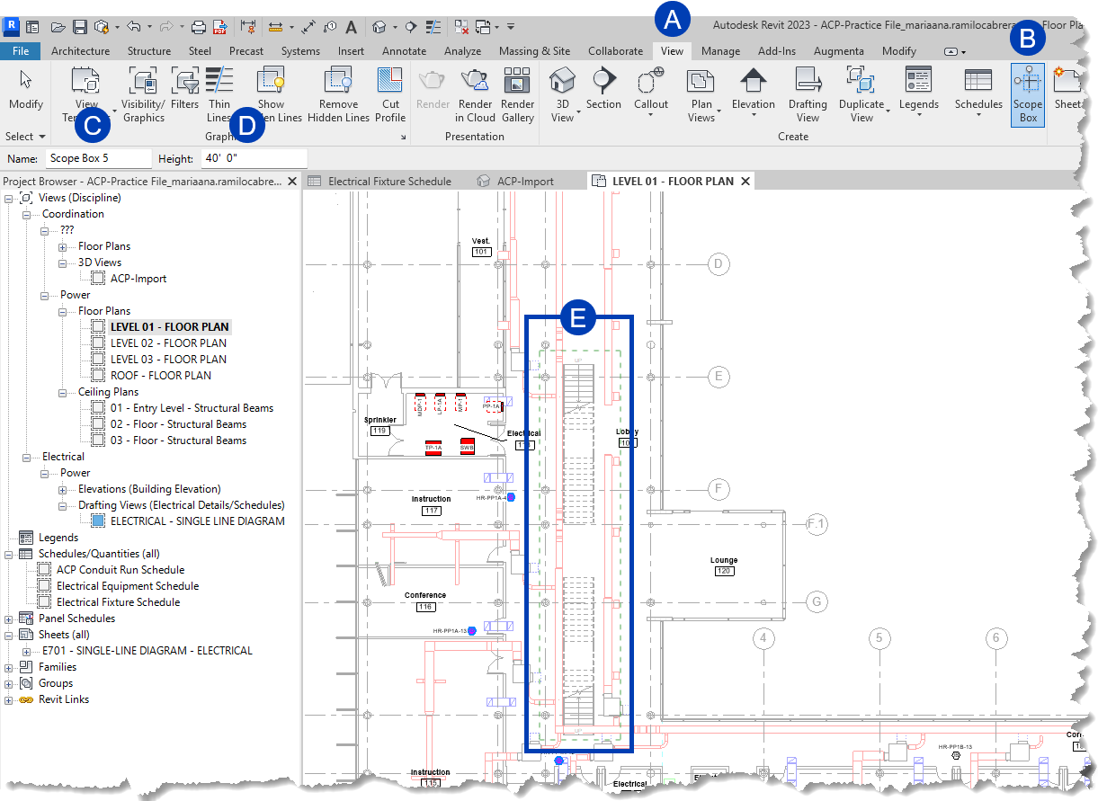 Create a Scope Box
Open the plan view in which you want to create a Scope Box.
Scope boxes can only be created in plan views.
Navigate to the
 View tab in the ribbon.
Select the
 Scope Box
  tool within the Create panel.
On the Options Bar, specify the
 Name and
  Height for the scope box
Scope Boxes can extend between floors.
A default Name will be assigned to the Scope Box if you don’t specify one, but it’s recommended to give it a descriptive name to easily reference it.
To draw a scope box, click in the view where you want to place the Scope box and drag to enclose the
 area you want.
 The scope box will display as a green dashed line around the boundary.
Click again to finish placing the scope box.
Assign a Scope Box to the ACP-Import view
 Open the ACP-Import view.
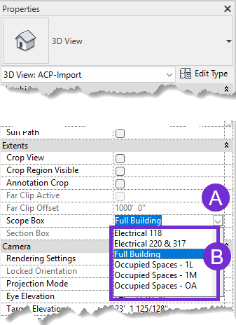
In the Properties palette, click the
 dropdown for Scope Box.
Select from the
 options.