The Model Viewer in an Interactive Study displays your Revit model with full navigation controls and the capability to draw Raceway Routes.
Navigation Controls
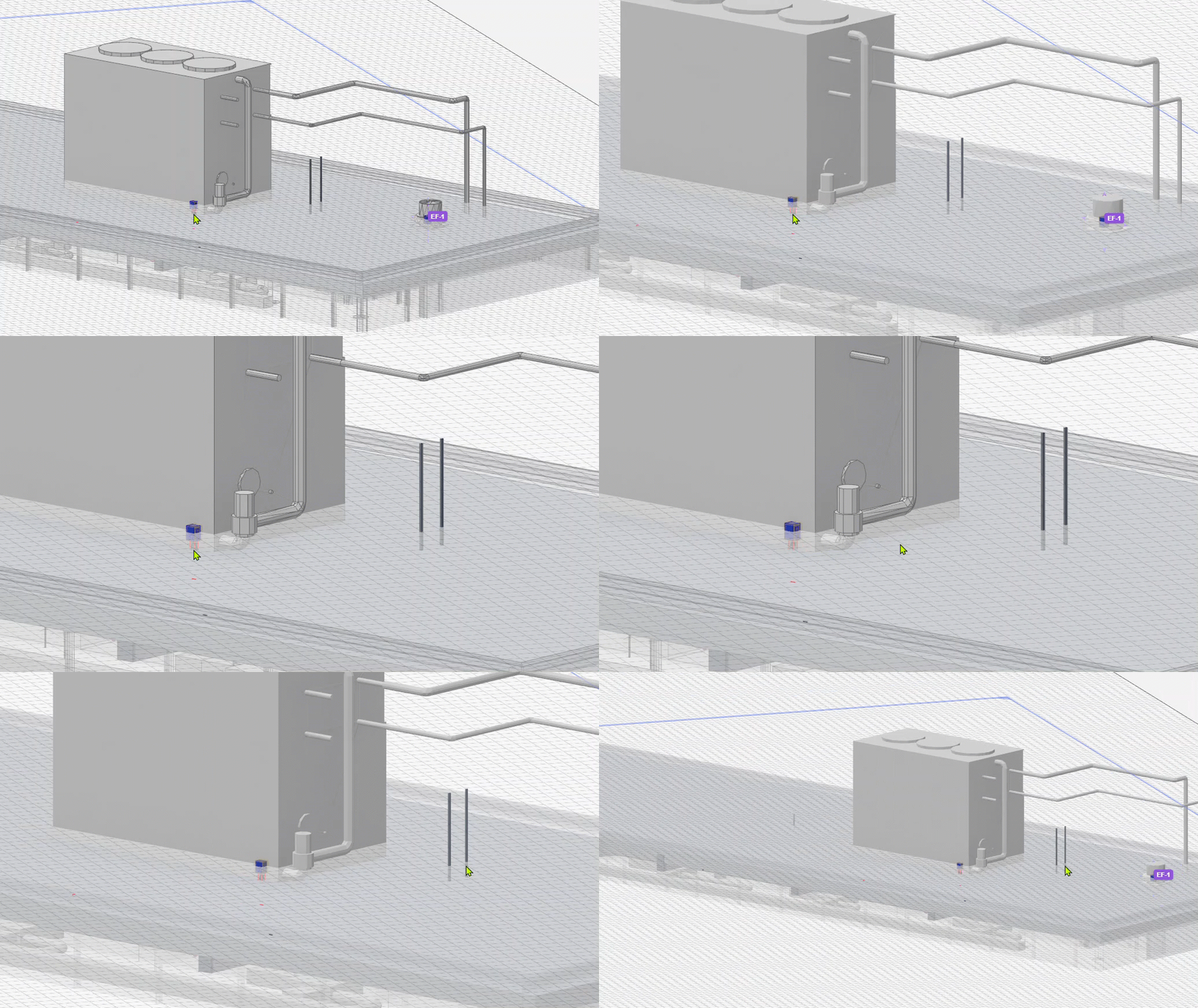
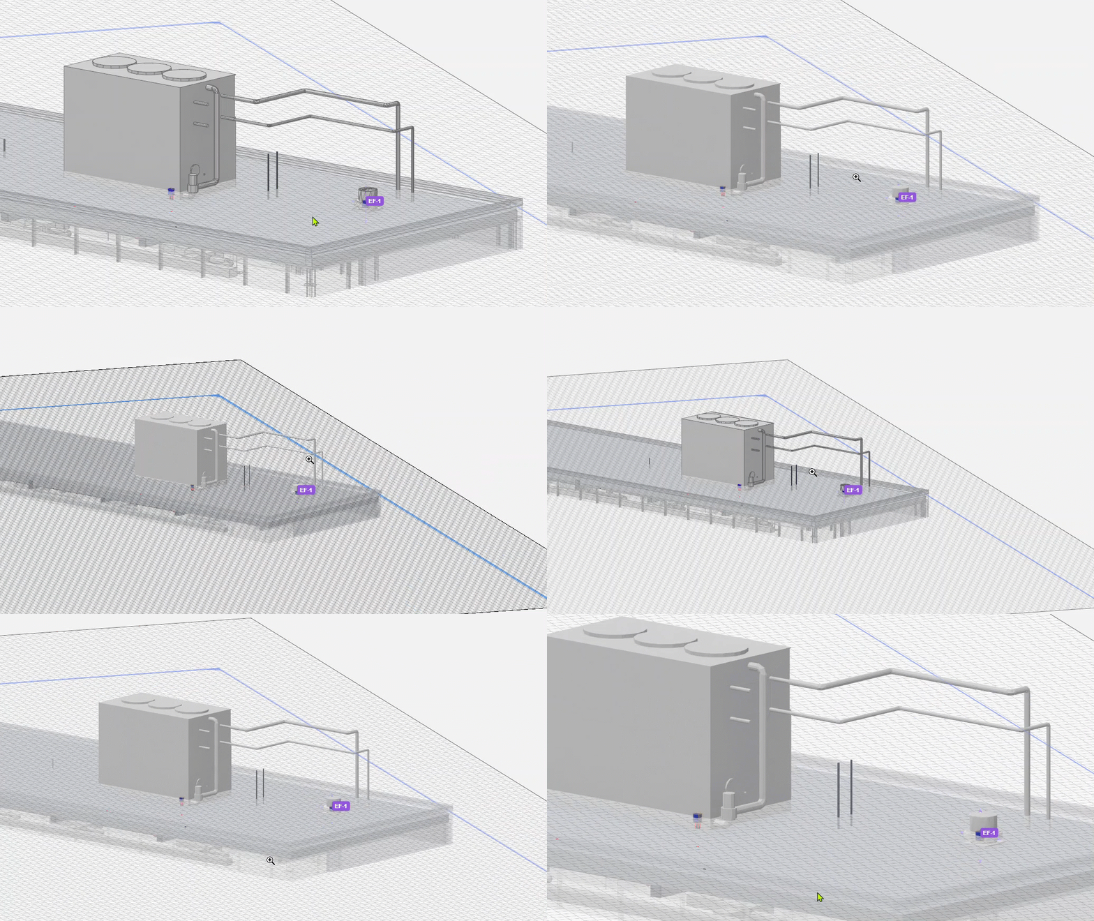
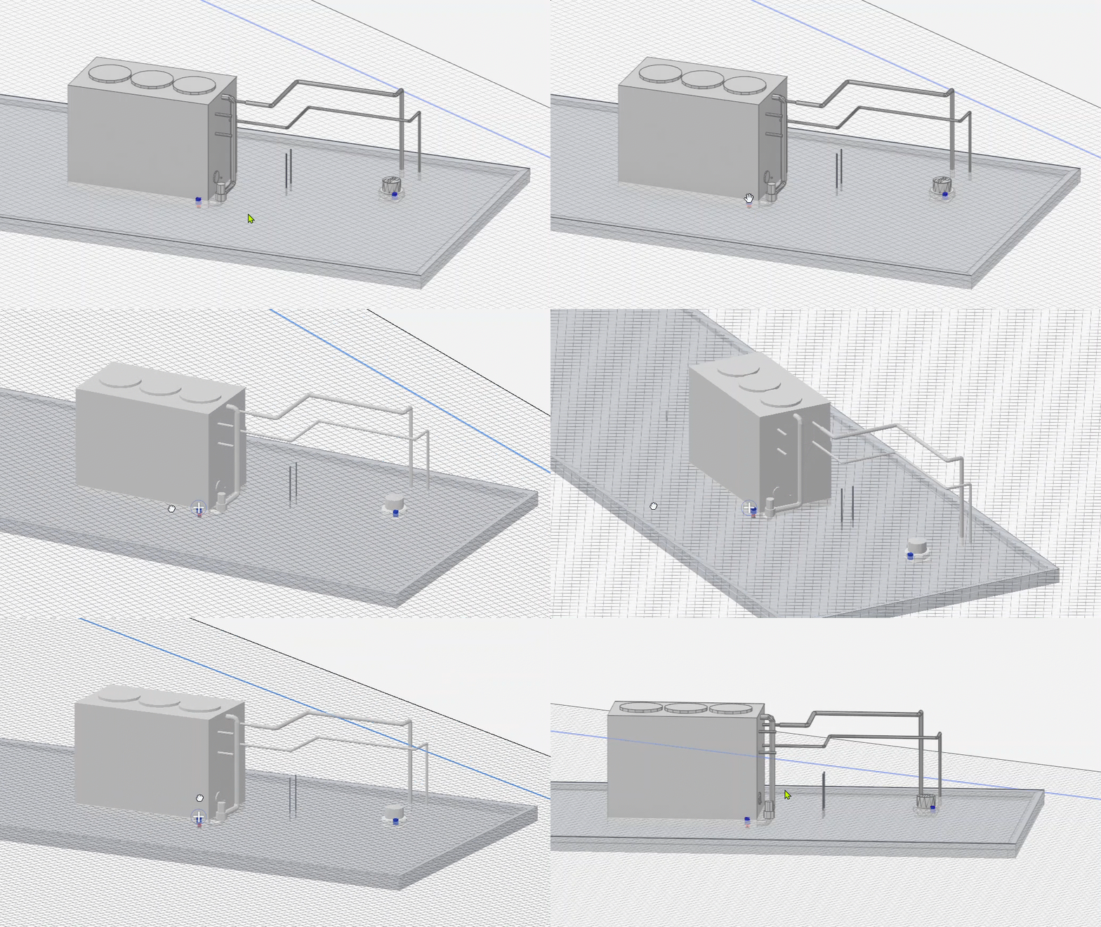
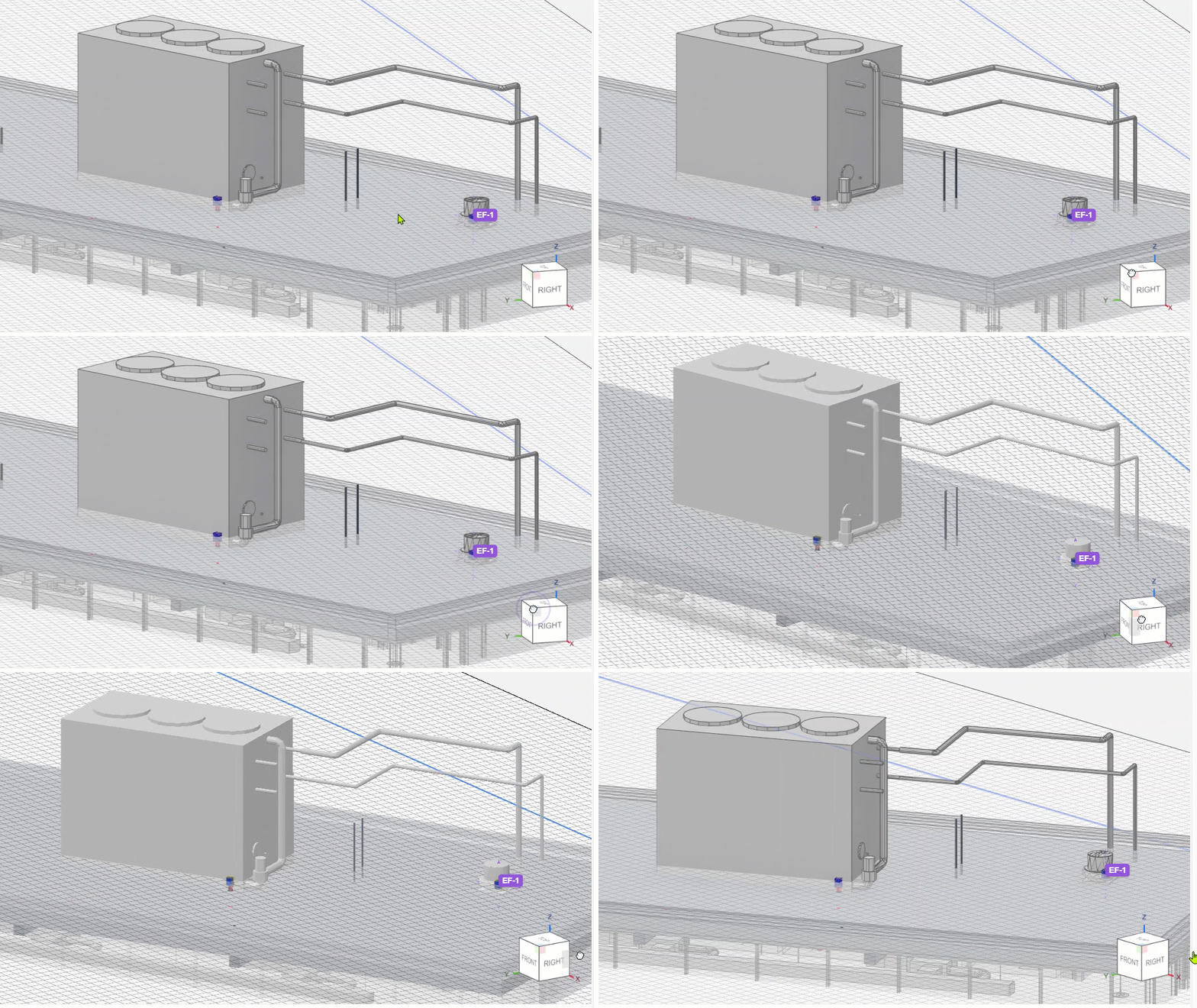
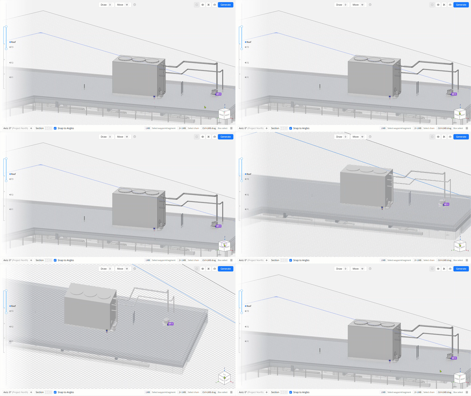
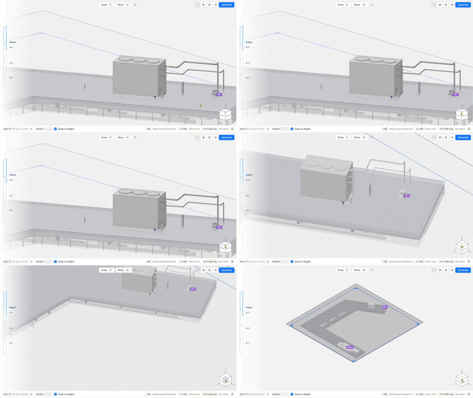
The Model Viewer supports intuitive movement using a combination of on-screen, and mouse controls which allow users to move within the space, orbit around specific points, and pan across views. This section outlines the different navigation controls in the 3D Model Viewer.
Action | Navigation Control (Click the dropdown |
|---|---|
Pan |
Scroll wheel click and drag |
Zoom to cursor |
|
Zoom to center |
|
Orbit |
Shift + Scroll wheel and drag |
 to see animation)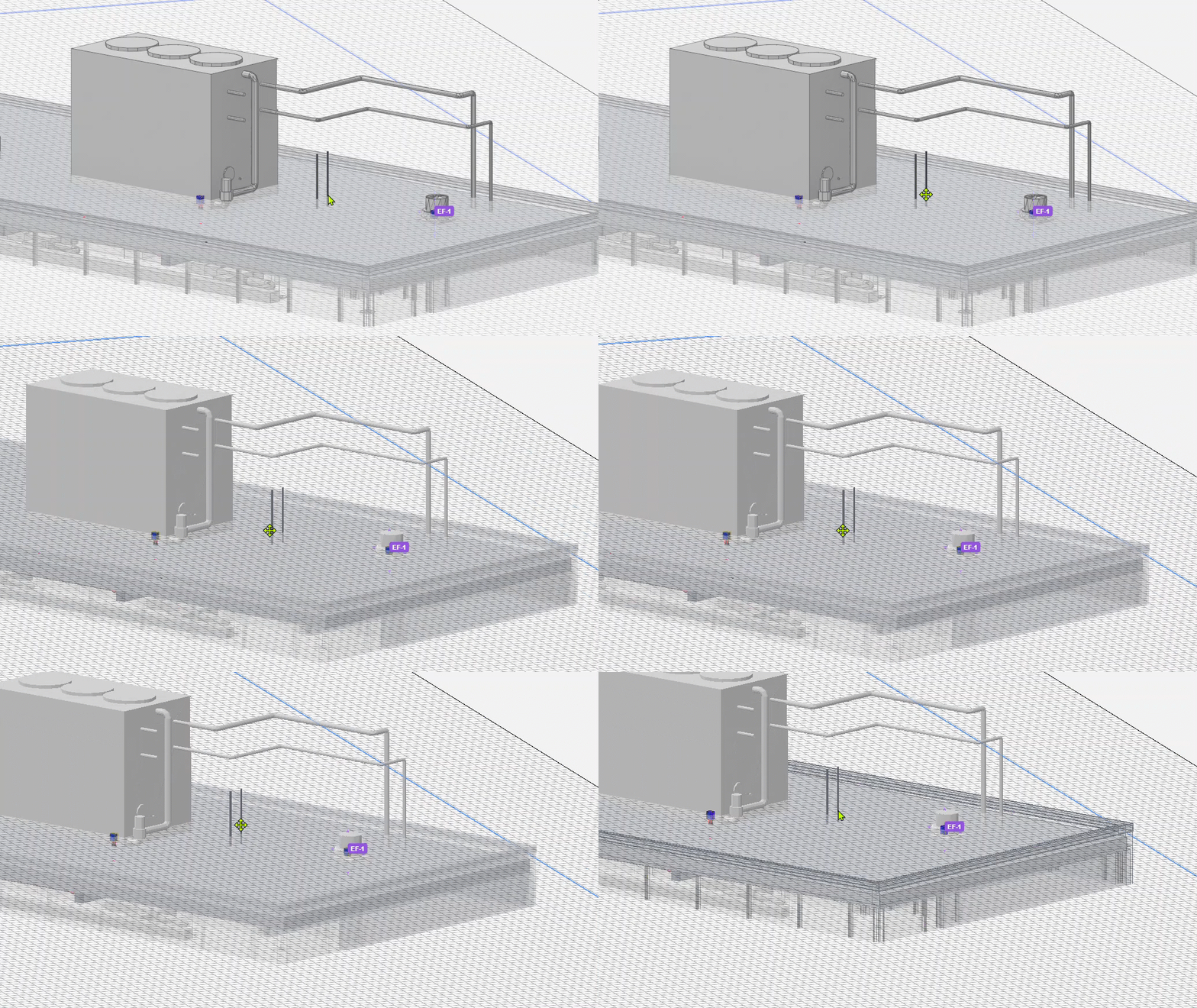
View Cube
The View Cube on the bottom-left corner of the Model Viewer allows you to easily switch planes on the 3D model by clicking on or dragging its labeled faces, edges, and corners.
Action | Navigation Control (Click the dropdown |
|---|---|
Orbit |
|
Re-orient |
|
Zoom to extents |
|
Model Setup Controls
The Model Setup controls in the Model Viewer include the Site Setup and Floor Setup tools.
.png)
 Site Setup
Setting up the site is one of the first steps of the Interactive Routing workflow. This includes importing the models and setting high-level rules for generating the conduit.
 Site Data
 Import Status - Displays whether the model has been imported, and if so, the date and time of the last import.
Import / Re-import - Import/re-import the Background Geometry / Electrical Model into the study.
Import all / Re-import all - Import/re-import both models at the same time.
 Design Rules
Minimum horizontal spacing - Specifies the minimum horizontal spacing between conduit in the generated solution.
Minimum vertical spacing - Specifies the minimum vertical spacing between conduit in the generated solution.
Floor Setup
.png) Floor Setup controls allow you to create and manage floors.
Floor Setup controls allow you to create and manage floors.
 Section Slider - Use the top and bottom sliders to vertically section the view, specifying the elevations of the top and bottom planes when setting up floors in the study.
New Floor - Appears when you adjust the Section Slider to create a new floor.
 Floor Selector - Displays the Edit Floor pane when clicked once, and crops the view to the top and bottom planes of the floor when double-clicked.
 Edit Floor Pane - Displays and allows editing of the floor details.
Name - Name of the floor.
Top Plane - The elevation of the floor’s top boundary, measured from 0ft of the building.
Work plane - The plane where segments are drawn by default at any given time. Its elevation may be adjusted any time by entering the elevation in the Work Plane textbox. The two tools below are associated with the Work Plane:
 Sample height - Set the Work Plane height to the same elevation as any existing waypoint, segment, or ACP Surface Connector Target in the study.
 Flatten to plane - Adjusts existing waypoints and segments within the set tolerance to the set elevation of the Work Plane.
Bottom Plane - The elevation of the floor’s bottom boundary, measured from 0ft of the building.
The blue boundary on the Bottom Plane is the Section Box which may be used to section the Site.
Delete floor
 - Deletes the floor.
The Top Plane of the deleted floor becomes the Top Plane of the floor below it.
 View Controls
View Controls allow users to control the visibility of different elements of the model, making it easier to focus on specific areas without other parts obstructing the view. The View Controls are organized into two sections: Background Geometry and Electrical Model. .png)
Reset view controls
.png) - Restores the default view controls settings.
- Restores the default view controls settings.Expand/Collapse toggle - Expands
.png) or collapses
or collapses  the view control group.
Section toggle - Show
.png) or hide
or hide .png) all View Controls within the group.
all View Controls within the group. View control information
 - Lists the elements/categories controlled by the View Control in a tooltip.
Visibility toggle - Show
.png) or hide
or hide .png) the parts of the model controlled by the corresponding View Control.
the parts of the model controlled by the corresponding View Control.Color Selector - Change the color of the parts of the model controlled by the corresponding View Control.
Transparency toggle - Controls if the corresponding elements/categories are solid
.png) or transparent
or transparent .png) .
.Section toggle - If turned on
 , the corresponding category will be cut off by the Section Box or Section Planes. If turned off
 .png) , the category will be excluded from the cut.
, the category will be excluded from the cut.
 Background Geometry
In the Background Geometry section, related Revit categories imported into the ACP study are grouped and controlled together.
For example, the Interior Ductwork category group includes Air Terminals, Ducts & Fittings, and Mechanical Equipment and MEP Fabrication categories in your Revit project.
 Electrical Model
The view controls in the Electrical Model section control the visibility of Model Viewer elements which are actively used in:
Creating raceway routes
Viewing the conduit solution once generated
Reviewing issues the generated solution may have
The Electrical Fixtures and Electrical Equipment categories are imported from your Revit project, while the rest are generated by ACP within the study.
Categories | Description |
|---|---|
Electrical Fixtures | Elements under the Electrical Fixtures category in the study. |
Electrical Equipment | Elements under the Electrical Equipment category in the study. |
Solutions | Generated conduit solution in the study.
|
Surface Connectors | Visualizes the ACP Surface Connectors on the face(s) of each electrical element where conduits can be routed.
|
Raceway Segment | Two types of segments in the study:
|
Issues | Flags issues or variations within the study which impact the ability of ACP to generate the conduit solution as drawn. These should be reviewed, tracked, or resolved.
|
Grid | A uniform pattern of 1’ x 1’ squares mapped across the Work Plane. |
Section Controls
There are multiple Section Controls you can use in the Model Viewer to cut through the Site.
Section Box
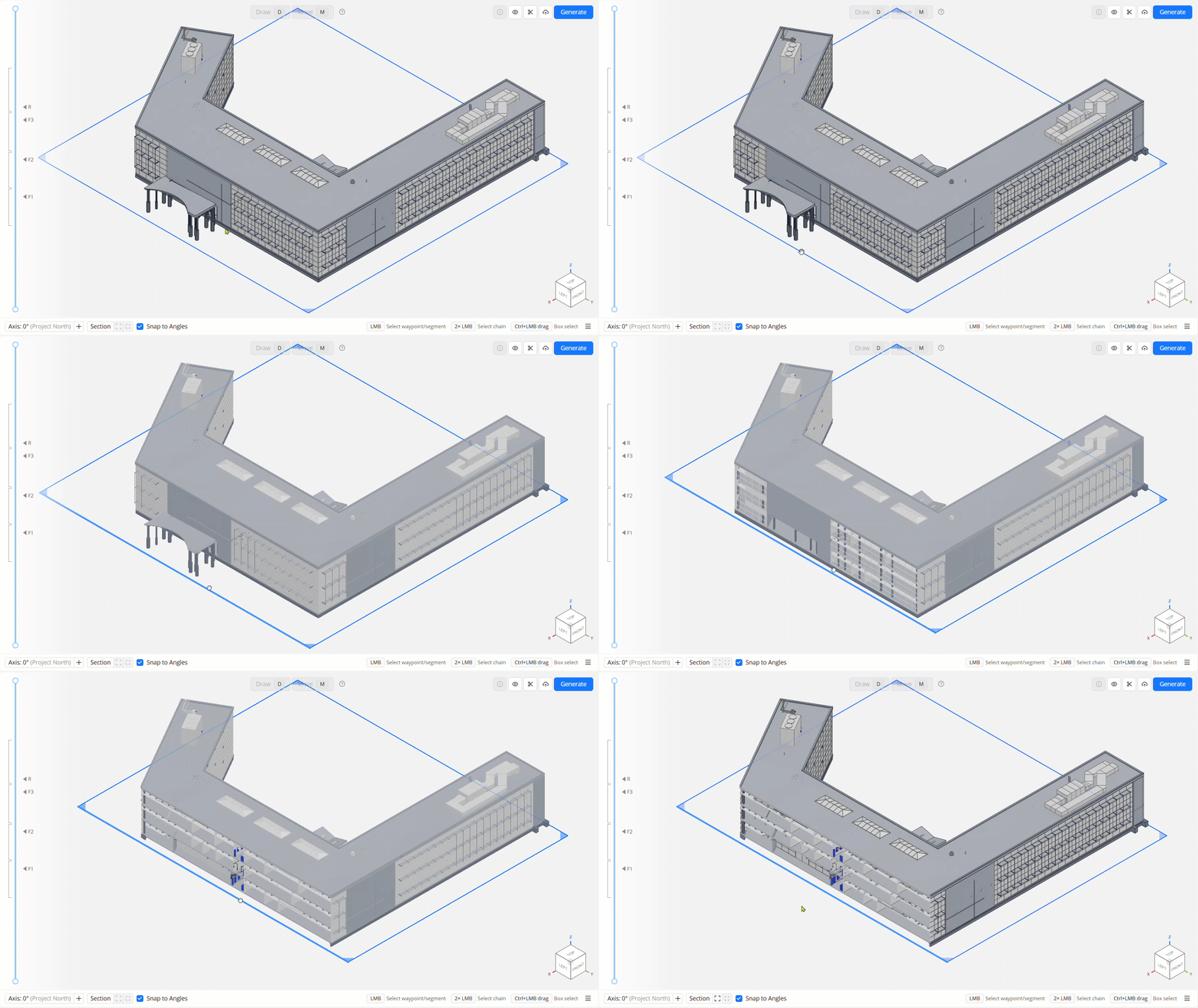
The Section Box is the primary control for cutting through the Site vertically on four sides. It’s always active and appears as a blue boundary attached to the bottom of the visible section of the Site.
By default, the boundary is set to an offset of 5 feet from the model extents on each side.
The Section Box is in the same orientation as the Site, and reorients whenever the Axis is changed.
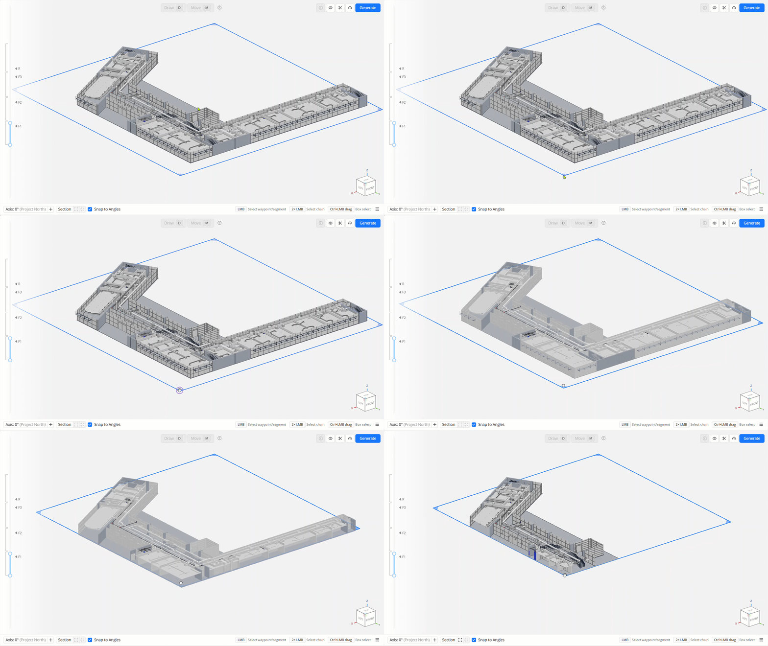
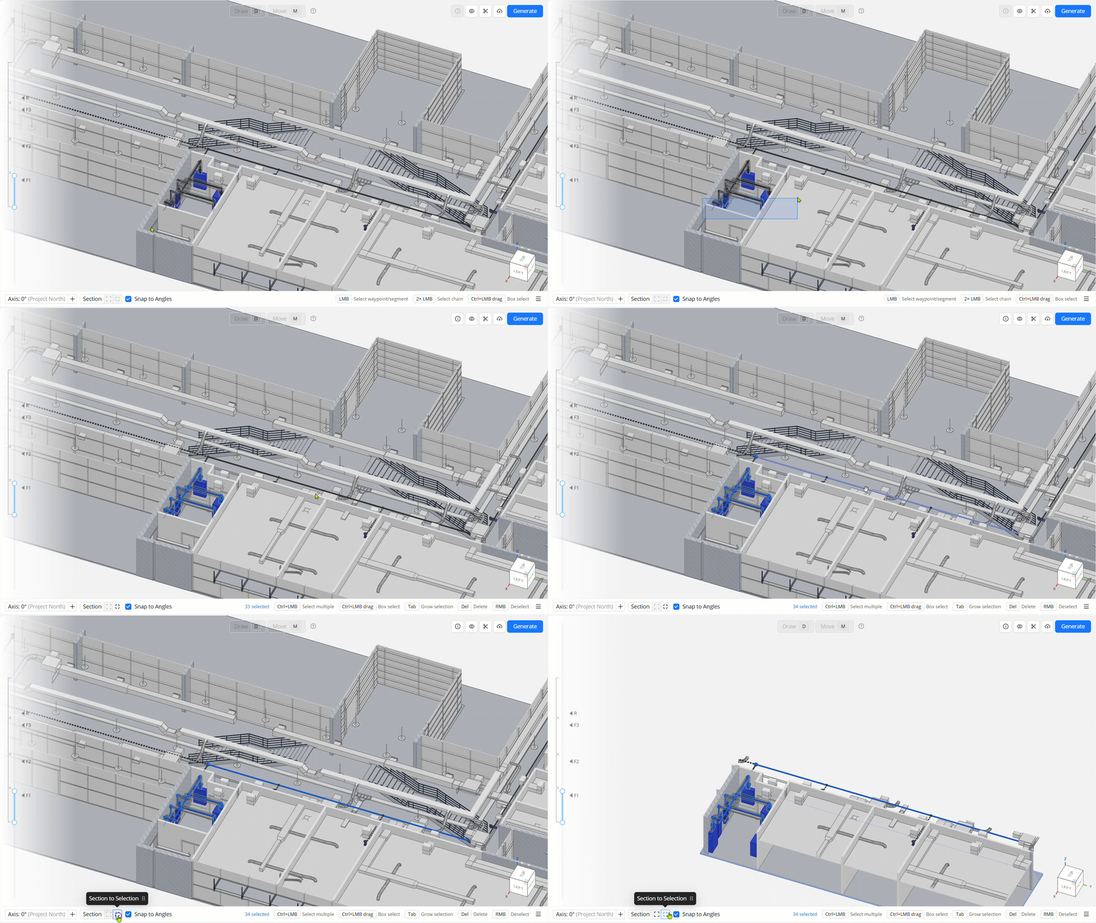
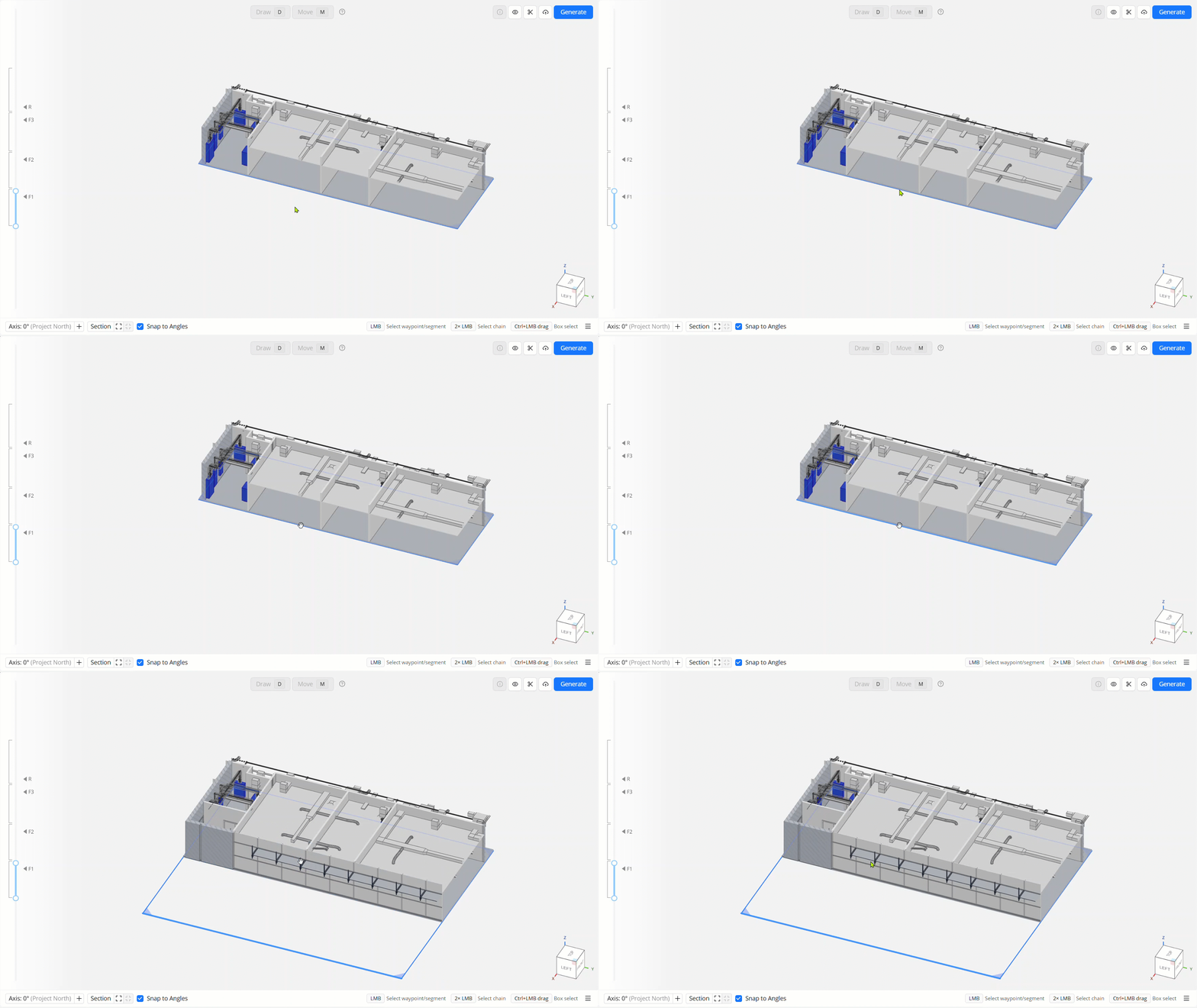
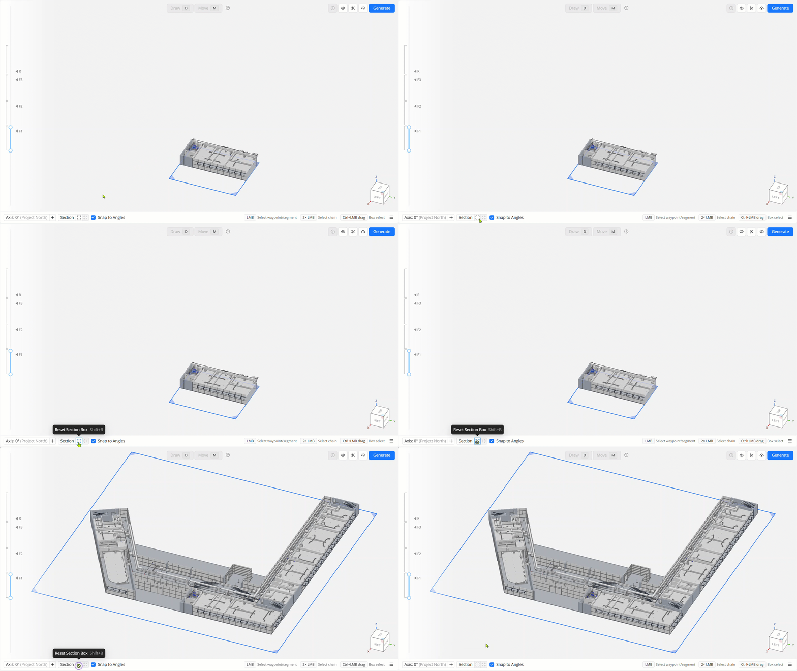
Vertical Section | Section Box Control (Click the dropdown |
|---|---|
Single side |
|
Two adjacent sides |
|
Section to Selection |
Shortcut: B |
Reset Edge |
|
Reset Extents |
Shortcut: Shift + B |
.gif) Section Slider
Section Slider
The Section Slider on the left-hand side of the screen allows you to cut through the entire model horizontally, making it quicker to view the top and bottom cross-sections at any elevation. The top and bottom handles of the Section Slider determine the elevation of the Top Plane and Bottom Plane when setting up floors in the study.
Hovering over the top or bottom handle displays its distance from the ground.
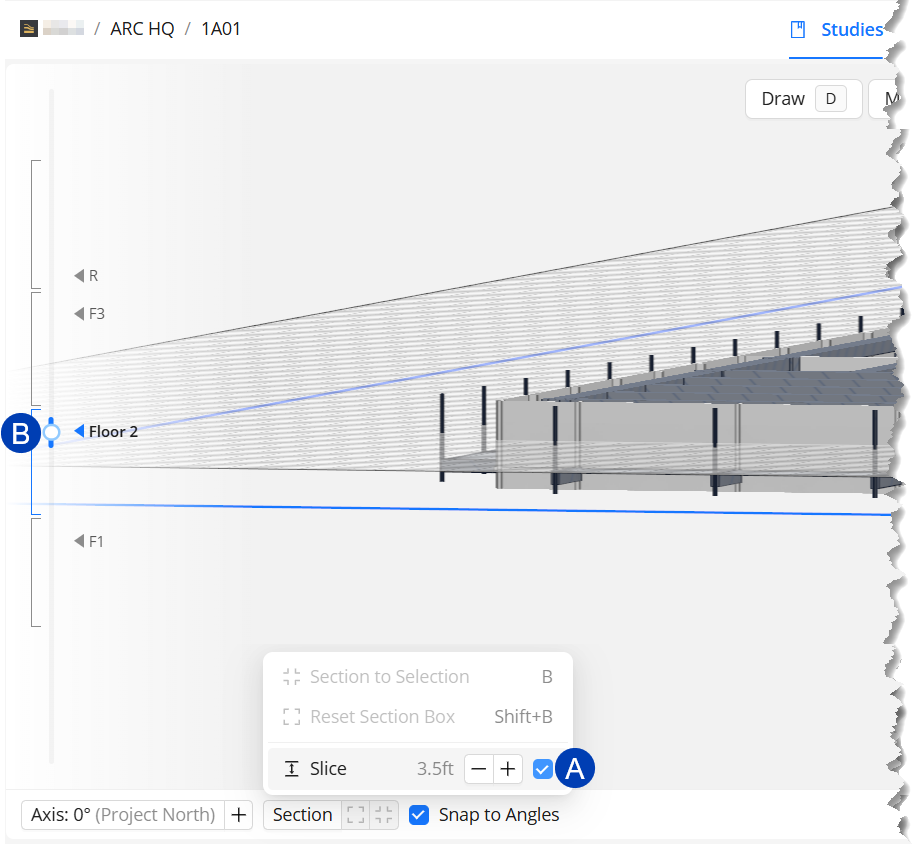
Slice
 The
The  Slice tool creates a horizontal cross-section of the Site which may be moved to different elevations of the Site using the
  Section Slider.
Upon activation, the Slice is initially centered at the Work Plane elevation.
Click and drag the handle of the Section Slider to move the Slice to different elevations of the Site.
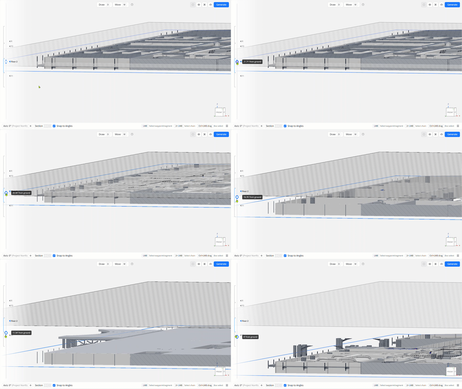
The default depth of the slice is 1’, and can be adjusted up to 6’ in 0.5’ increments.
The last depth is retained throughout the session, even when the slice is deactivated.
Section Planes
Section Planes allow users to create custom cut views, enabling detailed inspections of specific areas as you work throughout the Site. There can be many Section Planes placed in the model, and they can be deleted and re-placed as needed.
.png) The controls in the Section Planes panel are as follows:
The controls in the Section Planes panel are as follows:
 Place section plane - Places a Section Plane parallel to the current view of the model.
Section Planes are auto-numbered and may not be modified.
 Delete section plane - Deletes the selected Section Plane in the model. Once deleted, it can no longer be retrieved or undone.
Section plane controls - When you select a placed section plane, it will be shown in the model with its controls:
 Extend/retract plane - Represented by straight arrows, this adjusts the point along the plane to section through.
 Rotate plane - Represented by arches, this rotates the plane to a different axis.
Drawing Tools
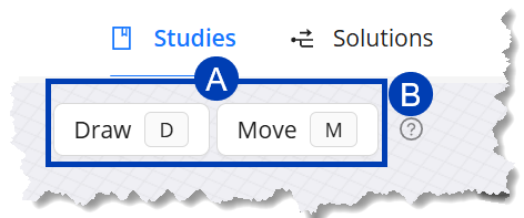 Different tools for drawing and managing segments are available in the Model Viewer. These help you in different stages of creating raceway routes.
 Mode Selector
Switch to Draw or Move mode. Whichever mode is active will be highlighted. If neither is highlighted, you are in Select mode.
 Hotkeys - Shows the list of hotkeys you can use while drawing in the study.
Info
 The Info
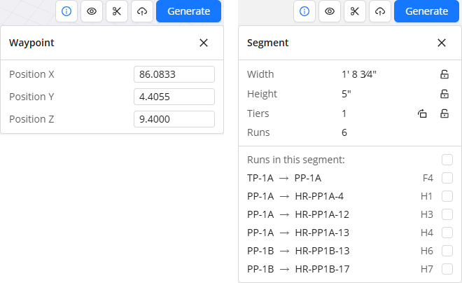
 .png) button opens the Info panel which displays and allows editing details of waypoints and segments.
button opens the Info panel which displays and allows editing details of waypoints and segments.
Waypoint
When a waypoint is selected, the Info panel will display its X, Y, and Z coordinates. These coordinates can be edited, allowing you to move the waypoint to a specific location.
Segment
When an Assigned Segment is selected, the Info panel displays the rack specifications and the raceways assigned to that segment.
Rack specifications - Displays and controls the dimensions of the Rack Preview on the segment. It also displays the number of raceways assigned to the segment.
Runs in the segment - Lists the Run IDs of the raceways assigned to the segment, specifying the Source and Destination for each raceway.
Selecting each checkbox selects the raceway in the Conduit Schedule, and all the segments in the entire run in the Model Viewer. This allows you to manage those segments simultaneously.
Status Bar
The Status Bar at the bottom of the Model Viewer provides the following guides and controls:
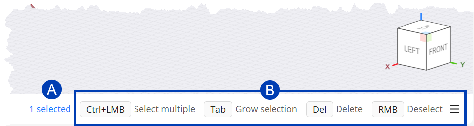 Quick Guide
The Quick Guide lists the  next actions you can take along with the corresponding controls.
The
 left-most value is the number of waypoints and segments selected.
.png) Angle Control
Angle Control
Orientation and angle snapping controls are found in the bottom left corner of the Model Viewer. These controls are helpful for drawing segments at an angle, as well as drawing in Off-Axis areas.
Angle list - Displays the default standard angles you can use in the study for orientation, as well as user-added angles.
The selected angle is the orientation that Proposed Segments will use.
Add Orientation - Add an angle to the list and re-orient the study to that angle.
Snap to Angles - Enable/disable snapping to standard bend angles when drawing segments.
Menu
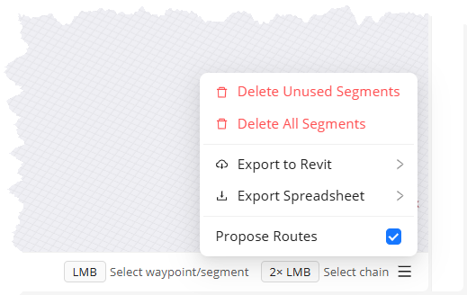 The Menu
  at the bottom right corner of the Model Viewer provides options to manage segments and generated solution.
Delete Unused Segments - Deletes all committed segments which aren’t assigned any raceways.
Delete All Segments - Deletes all committed segments in the study.
Export to Revit - Exports the generated conduit solution into your Revit project.
Export Spreadsheet - Export the Conduit Run Schedule of the generated solution into a .XLS file.
Conduit Schedule (.xls) - Exports the ACP Conduit Schedule into a .XLS file.
BOM - Exports the Bill of Materials for the generated solution.
Propose Routes - Enable/disable Proposed Routes in the study.
This follows the visibility setting of Proposed Segment in the View Controls panel.
Generate
The Generate  button starts the process of generating the conduit solution, which may done multiple times within a study.
This button will be disabled
 until at least one raceway is completed.
The Model Viewer in an Interactive Study displays your Revit model with full navigation controls and the capability to draw Raceway Routes.
Navigation Controls
The Model Viewer supports intuitive movement using a combination of on-screen, and mouse controls which allow users to move within the space, orbit around specific points, and pan across views. This section outlines the different navigation controls in the 3D Model Viewer.
Action | Navigation Control (Click the dropdown |
|---|---|
Pan |
Scroll wheel click and drag |
Zoom to cursor |
|
Zoom to center |
|
Orbit |
Shift + Scroll wheel and drag |
View Cube
The View Cube on the bottom-left corner of the Model Viewer allows you to easily switch planes on the 3D model by clicking on or dragging its labeled faces, edges, and corners.
Action | Navigation Control (Click the dropdown |
|---|---|
Orbit |
|
Re-orient |
|
Zoom to extents |
|
Model Setup Controls
The Model Setup controls in the Model Viewer include the Site Setup and Floor Setup tools.
Site Setup
Setting up the site is one of the first steps of the Interactive Routing workflow. This includes importing the models and setting high-level rules for generating the conduit.
Site Data
- Import Status - Displays whether the model has been imported, and if so, the date and time of the last import.
Import / Re-import - Import/re-import the Background Geometry / Electrical Model into the study.
Import all / Re-import all - Import/re-import both models at the same time.
Design Rules
Minimum horizontal spacing - Specifies the minimum horizontal spacing between conduit in the generated solution.
Minimum vertical spacing - Specifies the minimum vertical spacing between conduit in the generated solution.
Floor Setup
Floor Setup controls allow you to create and manage floors.
- Section Slider - Use the top and bottom sliders to vertically section the view, specifying the elevations of the top and bottom planes when setting up floors in the study.
New Floor - Appears when you adjust the Section Slider to create a new floor.
- Floor Selector - Displays the Edit Floor pane when clicked once, and crops the view to the top and bottom planes of the floor when double-clicked.
- Edit Floor Pane - Displays and allows editing of the floor details.
Name - Name of the floor.
Top Plane - The elevation of the floor’s top boundary, measured from 0ft of the building.
Work plane - The plane where segments are drawn by default at any given time. Its elevation may be adjusted any time by entering the elevation in the Work Plane textbox. The two tools below are associated with the Work Plane:
- Sample height - Set the Work Plane height to the same elevation as any existing waypoint, segment, or ACP Surface Connector Target in the study.
- Flatten to plane - Adjusts existing waypoints and segments within the set tolerance to the set elevation of the Work Plane.
Bottom Plane - The elevation of the floor’s bottom boundary, measured from 0ft of the building.
The blue boundary on the Bottom Plane is the Section Box which may be used to section the Site.
Delete floor
- Deletes the floor.The Top Plane of the deleted floor becomes the Top Plane of the floor below it.
View Controls
View Controls allow users to control the visibility of different elements of the model, making it easier to focus on specific areas without other parts obstructing the view. The View Controls are organized into two sections: Background Geometry and Electrical Model.
Reset view controls
- Restores the default view controls settings.Expand/Collapse toggle - Expands
or collapses the view control group.Section toggle - Show
or hide all View Controls within the group. View control information
- Lists the elements/categories controlled by the View Control in a tooltip.Visibility toggle - Show
or hide the parts of the model controlled by the corresponding View Control.Color Selector - Change the color of the parts of the model controlled by the corresponding View Control.
Transparency toggle - Controls if the corresponding elements/categories are solid
or transparent .Section toggle - If turned on
, the corresponding category will be cut off by the Section Box or Section Planes. If turned off , the category will be excluded from the cut.
Background Geometry
In the Background Geometry section, related Revit categories imported into the ACP study are grouped and controlled together.
For example, the Interior Ductwork category group includes Air Terminals, Ducts & Fittings, and Mechanical Equipment and MEP Fabrication categories in your Revit project.
Electrical Model
The view controls in the Electrical Model section control the visibility of Model Viewer elements which are actively used in:
Creating raceway routes
Viewing the conduit solution once generated
Reviewing issues the generated solution may have
The Electrical Fixtures and Electrical Equipment categories are imported from your Revit project, while the rest are generated by ACP within the study.
Categories | Description |
|---|---|
Electrical Fixtures | Elements under the Electrical Fixtures category in the study. |
Electrical Equipment | Elements under the Electrical Equipment category in the study. |
Solutions | Generated conduit solution in the study.
|
Surface Connectors | Visualizes the ACP Surface Connectors on the face(s) of each electrical element where conduits can be routed.
|
Raceway Segment | Two types of segments in the study:
|
Issues | Flags issues or variations within the study which impact the ability of ACP to generate the conduit solution as drawn. These should be reviewed, tracked, or resolved.
|
Grid | A uniform pattern of 1’ x 1’ squares mapped across the Work Plane. |
Section Controls
There are multiple Section Controls you can use in the Model Viewer to cut through the Site.
Section Box
The Section Box is the primary control for cutting through the Site vertically on four sides. It’s always active and appears as a blue boundary attached to the bottom of the visible section of the Site.
By default, the boundary is set to an offset of 5 feet from the model extents on each side.
Vertical Section | Section Box Control (Click the dropdown |
|---|---|
Single side |
|
Two adjacent sides |
|
Section to Selection |
Shortcut: B |
Reset Edge |
|
Reset Extents |
Shortcut: Shift + B |
Section Slider
The Section Slider on the left-hand side of the screen allows you to cut through the entire model horizontally, making it quicker to view the top and bottom cross-sections at any elevation. The top and bottom handles of the Section Slider determine the elevation of the Top Plane and Bottom Plane when setting up floors in the study.
Hovering over the top or bottom handle displays its distance from the ground.
Slice
The Slice tool creates a horizontal cross-section of the Site which may be moved to different elevations of the Site using the Section Slider.
Upon activation, the Slice is initially centered at the Work Plane elevation.
Click and drag the handle of the Section Slider to move the Slice to different elevations of the Site.
The default depth of the slice is 1’, and can be adjusted up to 6’ in 0.5’ increments.
The last depth is retained throughout the session, even when the slice is deactivated.
Section Planes
Section Planes allow users to create custom cut views, enabling detailed inspections of specific areas as you work throughout the Site. There can be many Section Planes placed in the model, and they can be deleted and re-placed as needed.
The controls in the Section Planes panel are as follows:
- Place section plane - Places a Section Plane parallel to the current view of the model.
Section Planes are auto-numbered and may not be modified.
- Delete section plane - Deletes the selected Section Plane in the model. Once deleted, it can no longer be retrieved or undone.
Section plane controls - When you select a placed section plane, it will be shown in the model with its controls:
- Extend/retract plane - Represented by straight arrows, this adjusts the point along the plane to section through.
- Rotate plane - Represented by arches, this rotates the plane to a different axis.
Drawing Tools
Different tools for drawing and managing segments are available in the Model Viewer. These help you in different stages of creating raceway routes.
Mode Selector
Switch to Draw or Move mode. Whichever mode is active will be highlighted. If neither is highlighted, you are in Select mode.
- Hotkeys - Shows the list of hotkeys you can use while drawing in the study.
Info
The Info button opens the Info panel which displays and allows editing details of waypoints and segments.
Waypoint
When a waypoint is selected, the Info panel will display its X, Y, and Z coordinates. These coordinates can be edited, allowing you to move the waypoint to a specific location.
Segment
When an Assigned Segment is selected, the Info panel displays the rack specifications and the raceways assigned to that segment.
Rack specifications - Displays and controls the dimensions of the Rack Preview on the segment. It also displays the number of raceways assigned to the segment.
Runs in the segment - Lists the Run IDs of the raceways assigned to the segment, specifying the Source and Destination for each raceway.
Selecting each checkbox selects the raceway in the Conduit Schedule, and all the segments in the entire run in the Model Viewer. This allows you to manage those segments simultaneously.
Status Bar
The Status Bar at the bottom of the Model Viewer provides the following guides and controls:
Quick Guide
The Quick Guide lists the next actions you can take along with the corresponding controls.
The
left-most value is the number of waypoints and segments selected.
Angle Control
Orientation and angle snapping controls are found in the bottom left corner of the Model Viewer. These controls are helpful for drawing segments at an angle, as well as drawing in Off-Axis areas.
Angle list - Displays the default standard angles you can use in the study for orientation, as well as user-added angles.
The selected angle is the orientation that Proposed Segments will use.
Add Orientation - Add an angle to the list and re-orient the study to that angle.
Snap to Angles - Enable/disable snapping to standard bend angles when drawing segments.
Menu
The Menu at the bottom right corner of the Model Viewer provides options to manage segments and generated solution.
Delete Unused Segments - Deletes all committed segments which aren’t assigned any raceways.
Delete All Segments - Deletes all committed segments in the study.
Export to Revit - Exports the generated conduit solution into your Revit project.
Export Spreadsheet - Export the Conduit Run Schedule of the generated solution into a .XLS file.
Conduit Schedule (.xls) - Exports the ACP Conduit Schedule into a .XLS file.
BOM - Exports the Bill of Materials for the generated solution.
Propose Routes - Enable/disable Proposed Routes in the study.
This follows the visibility setting of Proposed Segment in the View Controls panel.
Generate
The Generate button starts the process of generating the conduit solution, which may done multiple times within a study.
This button will be disabled
until at least one raceway is completed.