Many factors influence how ACP routes conduit between a Source and Destination. Some of these factors come from Revit (such as Category and Part Type), while others are introduced by ACP (such as Enabled status).
This article outlines these variables and explains how each one affects the specific kinds of electrical elements within an ACP Project.
Revit categories
The element categories which may be used as a Source and Destination for each Raceway are Electrical Equipment and Electrical Fixtures.
Typically used to represent items such as panels, transformers, and other primary electrical equipment.
These elements are identified using the Panel Name parameter.
Represents electrical components, including end-point devices such as junction boxes and receptacles, as well as access-point devices such as pull boxes.
These fixtures require unique identifiers through the ACP_E_Fixture_ID parameter for identification within ACP.
This is because they have no default parameter for identification.
Excluded Geometry
Clearance Subcategory.png)
Electrical Equipment and Electrical Fixtures are often modeled with additional geometry to represent required clearances, which prevent other trades from routing content through those areas. However, this clearance geometry can interfere with ACP’s ability to route conduit to the equipment.
To support accurate conduit routing, any geometry assigned to a Subcategory of either of these categories, containing the word Clearance in its name, is automatically excluded during ACP Import.
Because this adjustment only affects the ACP import, it has no impact on the Revit model itself or on coordination with other trades.
.png)
Fine Detail Level
Electrical Equipment and Electrical Fixtures are imported into ACP at the Detail Level of  Medium to allow for accurate detection of connectors, while avoiding importing small internal components that could interfere with routing.
Any Electrical Equipment and Electrical Fixtures family set only to the Detail Level of  Fine will automatically be excluded when importing the Electrical Model.
Element identification
The parameters in the table below are used to identify Electrical Equipment and Electrical Fixtures in the Revit project for use in the ACP workflow.
Parameter | Applied Revit Category | Description |
|---|---|---|
Panel Name | Electrical Equipment | A Revit-native parameter which exists in every Revit project. Used to identify each unique piece of electrical equipment. |
ACP_E_Fixture_ID | Electrical Fixture | A shared project parameter added to the Revit project during Initialization. Used to identify Electrical Fixtures for use in the ACP workflow. |
ACP_C_Enabled | Electrical Equipment Electrical Fixtures | A shared project parameter added to the Revit project during Initialization. If this parameter is set to Yes, the electrical elements will be seen as a potential source and/or destination in the ACP Electrical Model. |
ACP Surface Connector
.png)
Depending on the electrical element’s Part Type and Category, ACP generates Surface Connectors on faces where conduit may terminate, enforcing realistic physical constraints when connecting electrical elements to the rack.
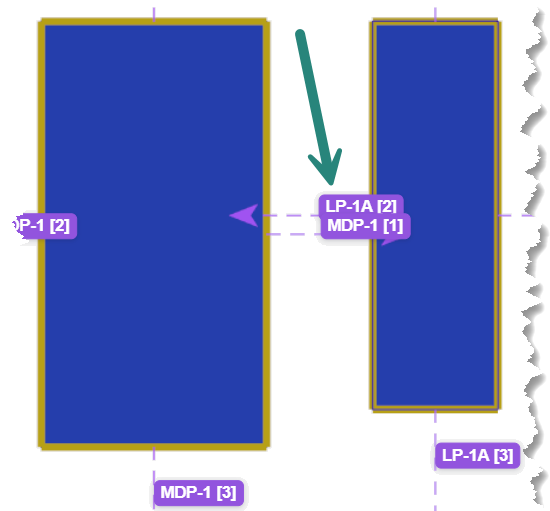
ACP Surface Connectors are visualized in the Model Viewer once you’ve imported your Electrical Model into your Interactive Study in ACP. By default, ACP Surface Connectors appear as yellow transparent boxes attached to the element’s face(s).
Each ACP Surface Connector has a Target in the middle where conduit may terminate. Targets are the purple arrows protruding out of ACP Surface Connectors. To easily identify which element the Target is for, especially for electrical elements placed close together, each one is labeled with the associated element ID and a number indicating the face it’s attached to.
Number | Face |
|---|---|
[0] | Top |
[1] | Right |
[2] | Left |
[3] | Bottom |
The ACP Surface Connector is entirely different from the Revit-native Conduit Connector
typically used to connect elements within the Revit conduit system. These Revit-native Conduit Connectors are ignored in the ACP conduit modeling workflow as they may introduce complications in conduit routing.

PRO TIP:
To make ACP Surface Connectors more visible in the Model Viewer, you can use the color selector
and transparency toggle
in the
View Controls panel for
Surface Connectors to change its color and transparency.
Electrical Equipment
Electrical Equipment such as Panelboards & Other Panels, Transformers, and Switchboards each have specific rules for how and where conduit may be connected. To handle these differences, ACP references the Part Type parameter within the Electrical Equipment family. This parameter allows ACP to distinguish between different types of equipment and apply appropriate routing logic. Each part type is treated differently during the conduit routing analysis to reflect its unique connection requirements.
.png) For Panelboards and other panels, conduit connections may be made to the top, bottom, and both sides of the panel
For Panelboards and other panels, conduit connections may be made to the top, bottom, and both sides of the panel
.png) Unlike other equipment, conduit does not terminate directly on any face of the transformer. Instead, conduit is routed to terminate near the transformer and then connected using flex conduit (also known as a whip).
Unlike other equipment, conduit does not terminate directly on any face of the transformer. Instead, conduit is routed to terminate near the transformer and then connected using flex conduit (also known as a whip).
ACP Surface Connectors are generated within an offset of 12 inches from the sides of the Transformer.
Conduits can then terminate:
Straight into the top or bottom of these ACP Surface Connectors
Or with a 90° turn into the front or side connectors.
The Targets of a transformer are as follows.
Number | Transformer Side | Face |
|---|---|---|
[0] | Right | Top |
[1] | Right | Front |
[2] | Right | Side |
[3] | Right | Bottom |
[4] | Left | Top |
[5] | Left | Front |
[6] | Left | Side |
[7] | Left | Bottom |
.png) For Switchboards, conduit connections may be made to the top and bottom of the panel.
For Switchboards, conduit connections may be made to the top and bottom of the panel.
Switchboard Sections
ACP looks for and identifies individual elements in order to route conduit between each Source and Destination. Switchboards are often modeled as one single element containing multiple sections of that gear. In order for the conduit to correctly terminate at each section you will need to provide a family instance for each section of the gear, and identify each with a unique name in the Panel Name property.
ACP can identify individual shared families nested within a main family. This allows you to use a shared family to simulate a conduit window for each section of equipment within a single family, and ACP will recognize and route to those instances provided the following.
The nested family instances are set to Shared within the family parameters.
Shared families are treated as individual elements in the project, allowing them to be scheduled and assigned properties independently from the host family.
They belong to the categories ACP supports (IE: Electrical Equipment or Electrical Fixtures).
Each instance is manually selected within the Revit project and enabled using the ACP_C_Enabled parameter.
Each instance is manually selected within the Revit project and given a unique name using the Panel Name parameter.
It’s up to you to decide whether this approach is more efficient than modeling each section as a separate family instance.
Because the Revit part type Equipment Switch does not include the default Panel Name parameter, it is not supported in the ACP workflow. To ensure conduit can be modeled to these devices, use the Other Panel part type for disconnects and similar switches.
Because ACP connects segments to the center of the Surface Connectors, creating side-to-side connections for Sources and Destinations which don’t align may create odd routing, Unknown parts, or cause generation for that route to fail entirely.
In these cases it may be easier to create side-to-side connections once conduit has been exported into your Revit project.
To better track these side-to-side connections which should be ignored while routing in ACP, and to easily reference which raceways need to be connected once the generated conduit is exported into your Revit project, follow the steps below:
Once the problematic side-to-side connections are identified,
deactivate the raceway within the Conduit Schedule.
Add a
note in the Conduit Schedule for each raceway which will require manual side-to-side connections in Revit.
Once you’ve generated the conduit and exported it into your Revit project,
search the Conduit Schedule for the note you entered in the previous step.
This filters the Conduit Schedule to show only the raceways which require manually creating side-to-side connections in Revit.
Manually create the side-to-side connections in your Revit project.
.png) Bottom face connections
Bottom face connections
To control routing at the bottom of an Electrical Equipment, you can use the ACP_E_Target_Bottom_Face parameter added to your Revit project during Initialization.
When unchecked, this parameter disables the ACP Surface Connector on the bottom face, preventing any bottom-face connections.
.png) Electrical Fixtures
Electrical Fixtures
In Revit, the Electrical Fixtures category typically represents access-point devices like pull boxes and end-point devices like junction boxes and receptacles.
In the ACP workflow, this category is most often used for junction boxes, whether a Home Run box or a larger pull box. Junction boxes have strict rules about which faces can connect to conduit. ACP lets you control which faces have ACP Surface Connectors based on the location of the Revit Electrical Connector.
The face where the Revit Electrical Connector is placed is the Back Face of the box once placed in the project. The opposite face then becomes the Front Face, and each adjacent face is considered a Side Face.
The Back Face, and each Side Face are considered routable. ACP will apply ACP Surface Connectors to these faces.
.png)
.png)
Because ACP does not utilize the Revit Electrical Systems, the properties of the Electrical Connector will in no way impact how the ACP interacts with the element.

ERROR: Missing Electrical Connector
When importing the Electrical Model with an enabled Electrical Fixture which does not contain a Revit Electrical Connector, the
Missing Electrical Connector error will be displayed in the pop-up when you click the
Issues button after the import.
Click here for steps to clear this error.
From the details, click the
link button of the element instance.
This will select the element and zoom to it within your Revit project.
Do either of the following to resolve the error:
Add a Revit-native Electrical Connector to the element’s family
Replace it with an element belonging to a family which already includes a valid Electrical Connector.
After ensuring that the connector is correctly placed, re-import the Electrical Model.
Repeat the steps above for all instances without an Electrical Connector.
Note: The Electrical Model is not successfully imported until the timestamp is displayed as shown.
.png)