When projects have specific needs, requirements, or rules that can’t quite be captured with the Automated Routing process of ACP, users can take full control over conduit placement with Interactive Routing in ACP. With minimal effort, users can draw the routes for the racks in the exact location that conduits should follow in the project, and ACP provides insight into space requirements and potential collisions against the Background Geometry. Once the routes are drawn, ACP handles the rest, analyzing the schedule inputs, modeling all of the conduit and bends, and organizing the conduit runs into racks. With the speed and flexibility of Interactive Routing, users are able to quickly modify routes and generate conduit solutions multiple times, exploring different routing options with ease.
Here are some helpful tools when using an Interactive Study to generate conduit routes:
Rack Preview - Visualizes the space to be occupied by the racks and conduits based on your Input Schedules.
Clash Detection - Highlights in red Assigned Segments intersecting an obstruction.
Proposed Routes - Suggested routes showing the shortest route between a Raceway’s Source and Destination.
This article covers the end-to-end process of using an Interactive Study to generate conduit routes.
Prepare the Revit project
The first step in preparing a Revit project for Import into ACP is to initialize it using the ACP Revit add-in. This step adds the necessary parameters, creates essential views, and applies key settings required to support the ACP workflow.
Prepare your Revit project for interactive routing by following the steps below.
.png)
In the
 Augmenta tab, click the
  Launch ACP tool.
In the pop-up window, log in with your credentials.
This enables the
 Initialize Project tool within the Augmenta tab.
Click the Initialize Project tool.
This adds the necessary parameters and views required in ACP.
Modify the ACP-Import view to determine which elements get imported as Site Data.
Refer to the Setting up the ACP-Import view article.
Create a new Interactive Study
.png) Interactive routing tools in ACP are only available in Interactive Studies.
Interactive routing tools in ACP are only available in Interactive Studies.
To create an Interactive Study, follow the steps below.
Within an ACP project, click the New Study dropdown button.
From the dropdown options, select New Interactive Study (Beta).
In the Create Interactive Study pop-up, enter the Study name and Description.
Click the Create button.
Duplicating an Interactive Study retains the tools associated with it.
Import Inputs
Once an Interactive Study has been created, it opens to a split-screen with the  3D Model Viewer displaying the Site Data on the left and the
  Schedule Inputs on the right.

PRO TIP: To adjust the display, hover your cursor between over the split-screen then use the controls which appear.
Adjust split-screen - Click and drag the split-screen line to adjust the display.
Expand screen - Expand either the 3D Model Viewer or Schedule Inputs to full screen.
Return to split-screen - Restore the default split-screen view to show both the 3D Model Viewer and Schedule Inputs
Orientation - Change the orientation of the screens: side-by-side or top and bottom.
.png) Schedule Inputs
Schedule Inputs
Follow the steps in the Creating Schedule Inputs article to create Schedule Inputs in your Interactive Study.
Existing Input Schedules in the ACP project, regardless of the study Type (Automatic or Interactive) they were previously used in, may be imported into the current study.
Site Data
The Site Data of an Interactive Study has the same two components as an Automatic Study’s Design Inputs: Background Geometry and Electrical Model.
Import these from the ACP-Import view of your Revit project by following the steps below.
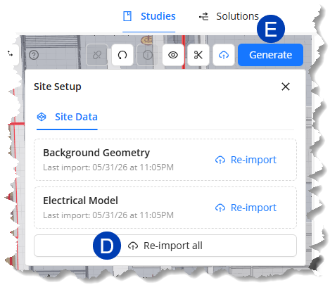
Click the
 Site Setup button.
In the dropdown Site Setup window, click the
 Import button for the Background Geometry and Electrical Model.
When the Site Data has been imported, the button will change into
 Re-import and the timestamp of the last import will be displayed.
 To import both site data at the same time, click the
 Import all / Re-import all button .
Once ACP finishes importing and processing the site data, the imported geometry will be displayed in the 3D Model Viewer.
Prepare the Site for drawing
For most raceways, the Source and Destination are on the same floor, making it practical to route floor by floor before connecting with risers. Set up the floors in the site to easily switch between isolated floor views when drawing the raceway routes. Setting up the floors also allows you to specify the elevation to snap to when drawing, essentially setting the default height for conduit routes.
Each floor has three planes:
Top Plane - The upper boundary of the floor. When the floor is selected, all geometry above this elevation is cropped from the view.
Work Plane - The default elevation where segments are drawn, similar to the Preferred Height.
Bottom Plane - The lower boundary of the floor. When the floor is selected, all geometry below this elevation is cropped from the view.
.png) Set up floors
Set up floors
Follow the steps below to set up floors in your site.
Modify the view so the floors are visible.
Use a Section Plane to create a cross-section of the site so the floors are visible.
Or use the View Controls to Hide
.png) the Exterior Walls in your site or make them Transparent
the Exterior Walls in your site or make them Transparent .png) .
.
Click and drag the
 top and
  bottom grips of the Section Slider so the model is cut to roughly the center of the slab of the floor above and the slab of the current floor.
Click the
 New Floor button which appears next to the Section Slider.
The first floor you create will be named Floor 1 by default. The floor number will increase as you create more floors.
In the Edit Floor pane that appears, you can configure the height of the different planes in the floor.
To set the Work Plane elevation, you can either manually specify the elevation or Sample height from the 3D view.
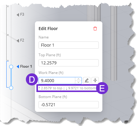 In the Edit Floor pane, enter the elevation in the
  Work Plane textbox or use the up and down arrows to specify the height.
The Work Plane’s
 distances from the Top Plane and the Bottom Plane are displayed below it. The distances are updated as you adjust the Work Plane’s elevation.
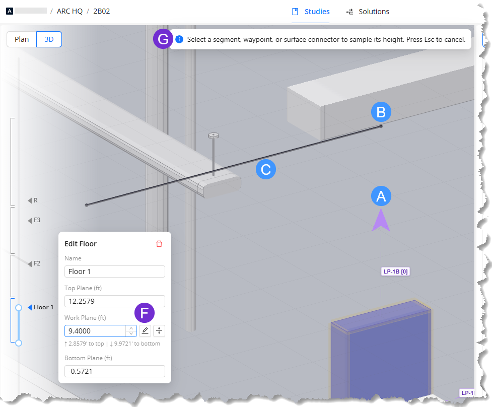 The Work Plane may be set to the same elevation as Surface Connector Targets (the purple arrow, such as
  , attached to a Source/Destination’s ACP Surface Connector) in the site. Waypoints (such as
  ) and segments (such as
  ) may also be sampled for Work Plane elevation if they’re already placed in the site.
Follow the steps below.
In the Edit Floor plane, click the
 Sample elevation button beside the Work Plane textbox.
A
 banner will appear at the top: Select a segment, waypoint, or surface connector to sample its height. Press Esc to cancel.
Select the segment, waypoint, or target you’d like to reference as the Work Plane elevation.
The Work Plane elevation will be the same as the selected element.
(Optional) In the Edit Floor pane, change the Name of the floor.
To start creating another floor, click and drag either the top or bottom grip so the New Floor button reappears.
Repeat the steps to create each floor in the building.
.png) Create raceway routes
Create raceway routes
Once the floors have been set up, the  View Selector and
  Mode Selector become enabled. The
  Status column in the Conduit Schedule will also update to display the routing status of each raceway.
The Status may be any one of the following:
.png) Run not active -
Run not active -  Inactive raceway
 Proposed route - Raceway not routed, proposed route available
 No route found - Raceway not routed, proposed route not available
 Routed - Raceway has been routed and segments are assigned.
Draw the main racks first.
Draw racks connecting the main racks to electrical rooms.
Connect Sources and Destinations into the main racks.
Draw raceway routes
Raceway routes are made up of multiple segments connected through shared waypoints.
Follow the steps below to manually draw raceway routes.
.png) Select the floor
Select the floor
In the 3D Model Viewer, select the
 Name of the floor with the raceways to draw routes for.
This crops the view to show the selected floor only and allows snapping to the set Work Plane of the floor.
Enter Draw mode
By default, the 3D Model Viewer is in Select mode.
To enter Draw mode, click the
 Draw button.
Or press D on your keyboard.
Select the view and axis to draw in
Segments may be drawn in any of the three axes and their corresponding perpendicular planes. In Draw mode, the cursor will change to show the selected axis or plane.
Follow the steps below to toggle between views and axes/planes.
Use the
 View Selector to switch between Plan view and 3D view.
The different axes are easier to see in 3D view.
To select the axis or plane you’d like to draw in, press its corresponding shortcut key:
Shortcut Key
Axis
Plane
Visualization (Using a Section Plane)
X
X-axis (left to right)
YZ-plane
Represented by the red controls
C
Y-axis (up and down)
XZ-plane
Represented by the green controls
Z
Z-axis (front to back)
XY-plane
Represented by the blue controls
Click here for visualization.
.png)
 : The X-axis is visualized as the purple line running along the same direction (left to right, and vice versa) as the red arrow in the section plane.
  : When you press X or the Spacebar while locked to the X-axis, you switch to the YZ-plane. The YZ-plane is formed by the Y- and Z-axes which are both perpendicular to the X-axis.
 To toggle between the selected axis and its corresponding plane, press the same shortcut key again, or press the Spacebar.
Pressing a different shortcut key switches to that key's corresponding axis or plane, whichever was last active. For example, if you're drawing in the XZ-plane then you press the X key, the active plane will switch to the YZ-plane.
Draw and connect segments
Left-click on the location where you’d like to place the first waypoint.
By default, the first waypoint snaps to the Work Plane.
Pressing a shortcut key before placing the waypoint will switch to a different drawing plane, though it will remain oriented to the Work Plane elevation.
Left-click on another location to draw a segment starting from the first waypoint.
PRO TIP: Drawing while locked to an axis allows you to draw straight along that axis. Switching to the axis' corresponding plane allows you to draw segments along the axes that define the plane, including segments that form standard conduit bend angles from the selected waypoint.
Continue placing waypoints to draw multiple connected segments.
Switch to either Plan or 3D view at any time using the View selector while still in Draw mode.
Toggle between different axis/plane at any time while drawing segments by pressing the corresponding shortcut keys.
Use the navigation controls to move through the model while in Draw mode.
Press Enter when finished.
Repeat the steps on this section to draw as many segments as necessary to connect the routes for all of the raceways in your floor.
Segments must intersect at shared waypoints to be connected.
Connect a Source/Destination to segments
 Raceways connect to Sources and Destinations through their Surface Connector Targets, which are the purple arrow protruding from some sides. The Targets are attached to the element’s ACP Surface Connectors which are visualized as yellow rectangles.
Follow the steps below to connect a Source/Destination to segments.
Hover your cursor over the element’s Surface Connector Target.
When the Target is highlighted, left-click on it to place a waypoint on the Target.
Move along the axis then click where you’d like to place the second waypoint to create the segment.
A purple rectangle will appear when you reach the Work Plane.
.png)
Repeat the steps to connect the other Sources and Destinations.
Once the raceway’s Source and Destination connects with each other:
The raceway’s status in the Conduit Schedule will change to Routed
.png) .
.In the 3D Model Viewer, the segments are assigned to the raceway route, and their Rack Preview is displayed.
The Rack Preview visualizes the estimated space required for the rack, and automatically adjusts as routes are connected to or removed from the Assigned Segment.
You can
 lock the Height and Width of the Rack Preview from the
  Info pane of the selected segment so its dimensions are no longer adjusted automatically.
Follow the steps below.
In the Notes column of your Conduit Schedule, indicate the floor where each raceway is placed.
Raceways on the same floor must have the same notes.
In the Search bar at the top, enter the floor you’re currently drawing routes for.
This filters the Conduit Schedule to show only the raceways on the entered floor.
Accept Proposed Routes
By default, the Proposed Segment category (appears as broken lines in the 3D Model Viewer) in the View Controls is set to Visible ![]() . The Proposed Segments in the viewer make up Proposed Routes which connect the Sources and Destinations together into routes based on the shortest distances of all enabled raceways in the Conduit Schedule. Proposed Routes adjust as segments are drawn in the site.
. The Proposed Segments in the viewer make up Proposed Routes which connect the Sources and Destinations together into routes based on the shortest distances of all enabled raceways in the Conduit Schedule. Proposed Routes adjust as segments are drawn in the site.
Proposed Routes may be accepted from the Conduit Schedule to create entire raceway routes. You can also accept specific Proposed Segments only in the 3D Model Viewer to create Committed Segments.
Because Proposed Routes are recalculated each time a segment is drawn in the model, they become helpful guides as you manually draw segments.
After you’ve drawn the main racks, the Proposed Routes often show the shortest route to connect a Source and Destination together through those racks. You can then accept the Proposed Routes, or draw more segments to further specify the route you’d like to take.
.png) Proposed Routes are made up of temporary segments in the 3D Model Viewer. To accept a Proposed Route for a raceway, each segment in the route must be individually accepted.
Proposed Routes are made up of temporary segments in the 3D Model Viewer. To accept a Proposed Route for a raceway, each segment in the route must be individually accepted.
Follow the steps below.
Switch to Select mode.
If you’re in Draw or Move mode, press the Esc key until neither is selected in the
 Mode Selector.
Hover over any
 Proposed Segment in the 3D Model Viewer.
Once highlighted, double-click to accept the segment and create a Committed Segment.
Repeat to accept other Proposed Segments in the Viewer.
Once you’ve accepted all the Proposed Segments making up a Proposed Route, the raceway’s status in the Conduit Schedule will change to Routed and the accepted segments become Assigned Segments with the Rack Preview.
View Controls button then disable the
Section Cut toggle for the Proposed Segment category group.
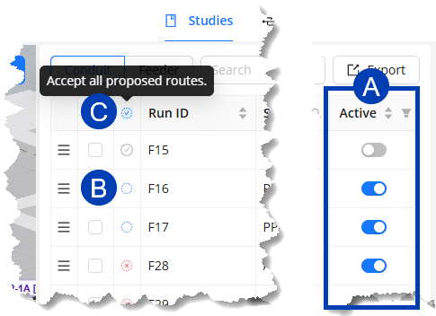 ACP displays Proposed Routes only for enabled raceways in the Conduit Schedule. When you accept a Proposed Route in the Conduit Schedule, all of the segments making up that route are accepted.
Follow the steps below to accept a Proposed Route(s).
In the Conduit Schedule, ensure that the
 Active toggle for the raceway is enabled.
The status of the raceway will change to Proposed Route
.png) or No route found
or No route found .png) .
.
Click the raceway’s
 Proposed Route status to accept it.
To accept all Proposed Routes, click the
 Status header.
Edit Segments
Any Committed Segment in the site may be edited at any time.
Move waypoints and segments
To move a waypoint or a segment, follow the steps below.
Enter Move mode by clicking Move on the Mode Selector.
Or press M on your keyboard.
(Optional) Switch to the axis or plane you want to move in by pressing its corresponding shortcut key.
Refer to the Select the view and axis to draw in section for the shortcut keys.
You can move the entire segment or just a waypoint.
.gif) To move the entire segment, click and drag the segment itself.
To move the entire segment, click and drag the segment itself.
Because the segment’s two waypoints move along with it, other segments connected to those waypoints will follow.
 To move only one end of a segment, click and drag the waypoint you’d like to adjust.
This allows you to change the slope or angle of the segment.
All segments connected to the point will adjust as well.
Delete segments
Any segment in the model may be deleted.
Enter Select mode.
If you’re in either Draw or Move mode, press Esc on your keyboard.
Delete a single segment or all unassigned segments.
To delete a single segment, follow the steps below.
Hover your cursor over the segment you’d like to delete.
Once the segment is highlighted, left-click on it to select.
Press Del on your keyboard.
.png) Unassigned segments don’t connect a raceway’s Source and Destination, and may get in the way while you’re drawing or navigating through the site.
Unassigned segments don’t connect a raceway’s Source and Destination, and may get in the way while you’re drawing or navigating through the site.
To easily clean up the view, simultaneously delete all Unassigned Segments, and their routes by following the steps below.
Click the
 Delete unassigned segments button.
In the pop-up dialog box, click the
 Delete button.
This action may be undone by pressing Ctrl + Z on your keyboard.
Working with Clash Detection
ACP analyzes the space each rack will occupy and flags any potential clashes. Unlike Automatic Routing, Interactive Routing generates conduit routes regardless of obstructions, giving you full control to decide which elements may be penetrated and which must be avoided.
Locate and identify obstructions
Assigned Segments make up the raceway route that connects a Source and Destination. They are visualized with a Rack Preview which shows the estimated space requirement to place the conduits connected to the same rack.
 The Clash Detection feature in Interactive Routing helps you locate Assigned Segments with an obstruction in their path, and the estimated space required for the conduit rack of the Rack Preview.
Follow the steps below to locate and identify obstructions along Assigned Segments.
Switch to
 3D view.
This lets you see both horizontal and vertical segments.
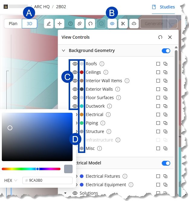
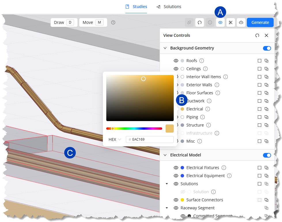
Click the
 View Controls button.
Ensure that the
 Visibility toggle for each category groups in the Background Geometry section are enabled.
(Optional) Click the
 color selector of each category group then choose a different color for each one.
This lets you easily identify each category in the site.
In the 3D Model Viewer, locate any segment that’s highlighted in red.
Review the entire length of the segment to find where it clashes with other geometry.
Walls aren’t considered as obstructions.
Once you’ve located and identified the obstructions, you can decide whether to route around the obstruction or allow conduit to penetrate it.
Route around obstructions
To modify Assigned Segments in the route so they avoid obstructions, follow the steps below.
Locate the obstruction blocking the Assigned Segment.
Switch to Draw mode by clicking the Draw button in the Mode Selector.
Or press D on your keyboard.
Draw a waypoint on either side (such as
 and
and  ) of the obstruction.
This isolates the
 obstructed portion of the segment so it’s the only portion highlighted in red.
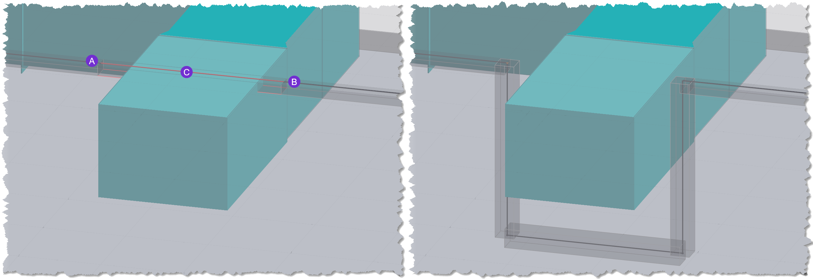
Delete the isolated portion.
Reconnect the remaining two segments by drawing the new segments around the obstruction.
Press the Shift key while drawing the segment to use standard bend angles.
Generate conduit routes
 In Interactive Routing, ACP generates a conduit route for each raceway with a Routed status in the Conduit Schedule when you click the Generate button. The generated conduits follow the route of the Assigned Segments for the raceway, and are detailed according to the specifications referenced by the raceway’s Feeder ID from the Feeder Schedule.
Modify generated conduit routes
The Assigned Segments used to generate  conduit routes may be modified at any time. Because the conduit generation is not live, conduits do not adjust their location until you click Generate again. When you do, the previously generated conduit routes for the raceway will be removed and the new routes will follow the newly drawn segments.
Follow the steps below.
Delete the Assigned Segment(s) for the conduit route you’d like to modify.
 Draw new segments for the new route you’d like for the conduit.
Ensure that the segment(s) you draw are fully connected and assigned a Rack Preview, indicating that it connects a Source and Destination.
Repeat for all the raceways you’d like to modify the generated routes for.
Select the
 Generate button to generate new conduit routes for the raceways.
The generated conduit route will follow the newly drawn segments.
the Solutions category group.
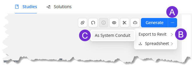
Export to Revit
 To export the solution into your Revit project, follow the steps below.
Hover your cursor over the
 ellipsis next to the Generate button.
From the dropdown options, select
 Export to Revit.
Select
 As System Conduit.
Combine Automatic and Interactive Routing
Combining the Automatic and Interactive Routing workflows provides you the efficiency of ACP’s generative AI while still having full control of the conduit routes. In Automatic Routing, ACP determines the optimal conduit routes for your project based on the specifications you set, and creates 12 unique solutions you can review. You may select a solution to be exported to your Revit project, which may then be used as a reference when you generate conduit routes using the Interactive Routing workflow.
Follow the steps below.
Generate solutions from an Automatic Study.
Once ACP finishes generating solutions, select the one you’d like to use and export it As System Conduit into your Revit project.
This solution will be will be imported as part of the Background Geometry which you may use as reference when you draw raceway routes in an Interactive Study later.
In your Revit project, prepare the ACP-Import view to ensure that the exported solution is visible in the view.
In an ACP project, create an Interactive Study.
Re-import all Site Data and provide the Schedule Inputs.
The conduit solution will be imported as part of the Background Geometry.
To easily see the conduit solution in the view, use the
 View Controls to change the
  color of the Electrical category group.
The same Conduit Schedule from the Automatic study may be used.
Prepare the site for drawing.
Trace the raceway routes from the conduit solution that you’d like to be a part of the final solution.
The

Draw a different raceway route for the conduit routes in the solution that you’d like to change.
For accurate Clash Detection, remove the conduit solution from the ACP-Import view of your Revit project then
 Re-import all of the Site Data of your Interactive Study.
The raceway routes you’ve already created will remain in the view while a version of the Site Data without the conduit solution, which previously triggered clash detection, is imported.
Once the status of all raceways in the Conduit Schedule is Routed
.png) , click the
, click the  Generate button.
The generated conduit routes from Interactive Routing may be modified at any time.
In your Revit project, remove the previously exported conduit solution.
Export the conduit routes generated from the Interactive Study into your Revit project.
(Optional) If the conduit routes need to be modified further once exported into your Revit project, you may use the Edit tools within the Augmenta tab.