The Background Geometry is one of the Design Inputs of a Study. In generating solutions, the Background geometry:
Includes all elements in your Revit model (linked or otherwise) which aren’t imported into ACP as part of the Electrical Model. It provides ACP with critical spatial context, including available space for conduit racks as well as obstructions such as walls, beams, and other trade elements. It also identifies supportable elements in the model, enabling ACP to generate conduit racks which are both clash-free and properly supported.
Background Geometry consists of all elements in your Revit project which aren’t part of the Electrical Model. These elements are derived from the following:
The main model you’re working in and have full control over
The linked models, such as architectural, structural, and other trades, which are brought into your project and typically have limited access
Below are the common modeling issues, ordered from most to least common, in the Background Geometry which cause routing issues in solution generation.
Issue | Failed Solution/Other | Unrouted Runs | Odd Routing |
|---|---|---|---|
✘ | ✘ | ✘ | |
✘ | ✘ | ||
✘ | ✘ | ||
✘ |
Once you’ve updated the Background geometry to resolve these issues, you can try re-importing it into an ACP study then Generate again to verify the routing issues have been resolved.
Excessive geometry
Excessive geometry in the ACP-Import view is the #1 cause of failed routes, odd routing, and overall solution failure. It’s also one of the most difficult issue to diagnose because each organization has different modelling practices, resulting to a wide range of Revit model configurations.
What it may look like in ACP
Unrouted Runs
When reviewing the Unrouted Runs in the 3D Solution Viewer, the Explored Space highlights areas which ACP explored while finding conduit routes. When Explored Space is shown in the Viewer, you may be able to identify obstructions which can’t be penetrated because these will not be highlighted.
The obstructions may appear as:
A gap between the source and destination.
A pinch point where the explored space seemed to almost connect but funnels to one very small point within the site.
PRO TIP: To identify any obstruction causing multiple Unrouted Runs, review the runs which should be routing within the same area together.
Similar patterns across multiple Unrouted Runs indicate a common obstruction.
The gaps and pinch points help narrow down problem areas in your Revit model which need to be addressed during review and ACP-Import setup.
Use Section Planes to get a better view of the area.
It may also be helpful to use the View Controls in the Viewer to identify the category of the obstruction.
Odd Routing
In a successfully routed raceway, excessive geometry may cause the conduit to take a path that’s contrary to how you would normally route through a specific area. Strange turns in the rack, odd elevation changes, or inconsistent penetrations, are good indicators that there’s an issue with the geometry in the ACP-Import view.
Solution Failure
ACP analyzes all of the geometry within the view when looking for supportability and available space. In addition to blocking possible routes, the white noise of excessive geometry (even below the Raceway Height Lower Clearance) can also substantially weigh down a model, resulting in significantly longer generation times, and even complete solution failure.
Reviewing the Revit model
Excessive geometry in your model may show up in a number of ways, including but not limited to the following:
Elements categorized in unexpected ways
Generic Models placed in the model as large clearance, space, or zone placeholders.
Elements used to map Egress routes throughout the building.
Railing systems are most frequently used, but other categories may have been used in your model.
Overly detailed Revit families in linked files, including but not limited to:
Specialty Equipment
Generic Models
Plumbing Fixtures
Lighting Fixtures
Furniture
Exterior decoration or site features
Elements outside exterior walls are not used in generating solutions and will only negatively impact the process.
Different categories may have been used for this.
Pre-placed hanger elements
These will block any possible ACP route, and should be removed.
Elements below the ceiling plane or Raceway Height Lower Clearance
Conduit doesn't require coordination with elements below the ceiling or the Raceway Height Lower Clearance.
PRO TIP: Review the ACP-Import view category by category to catch any sneaky geometry which may be miscategorized or hidden behind other elements.
In the Visibility/Graphics Overrides, turn off the Visibility of all categories except the one you want to review.
Use Schedules to track specific properties of elements or group of elements which should be hidden within the ACP-Import view.
Contact support@augmenta.ai for help or to request a Geometry Detail Report. Access to your model must be provided to create the report.
Resolving the Issue
.png) Any excessive geometry identified must be cleared in the ACP-Import view. There are multiple ways to do this, including the following:
Any excessive geometry identified must be cleared in the ACP-Import view. There are multiple ways to do this, including the following:
Modify the ACP-Import view to hide or filter out the excess geometry.
Disable the visibility of the categories in the main model, or directly in the Display Settings of Revit Links
Create and apply a view filter with Filter Rules based on the properties of the categories which should be hidden from the view.
View filters are likely the best way to control visibility given the flexibility they offer since many categories have both necessary and excessive geometry in them.
Use May Route Box to create penetrations in any excess geometry, which need to remain in the view for additional collision avoidance.
Turn off the visibility of any geometry which is neither supportable nor relevant for collision coordination of ACP conduit.
Create an “Excessive Geometry” view filter to capture all problematic geometry.
Because multiple rules may be applied to a view filter, you can use a single view filter to control the visibility of excessive geometry in the ACP-Import view.
Incorrect wall function setting
The Routing Through Walls design rule allows ACP to route conduits perpendicularly through walls within a scoped area. This design rule also limits routing within the interior of the building if its Automatically detect exterior walls setting is toggled on. For ACP to recognize exterior walls, the Function parameter of the wall type must be set to Exterior.
If the Function parameter of the wall is set incorrectly, ACP will not be able to identify exterior walls. Combined with the Routing Through Walls design rule configured for ACP to Automatically detect exterior walls, which prevents routing through exterior walls, incorrect wall function setting may cause the following:
Interior walls marked as exterior can block valid conduit routes.
Exterior walls marked as interior may allow unintended penetrations and cause incorrect routing.
What it may look like in ACP
Unrouted Runs
Walls which are incorrectly set to Exterior walls become unexpected obstructions when the Automatically detect exterior walls setting of the Routing Through Walls design rule is toggled on. Just as with Excessive Geometry, these obstructions will present as a break in the Explored Space between the Source and Destination.
Odd Routing
Incorrectly set function of interior or exterior walls may also force ACP to route conduit in less than ideal paths, such as outside the building, or make odd saddles around sections of the building.
Reviewing the model
 In ACP
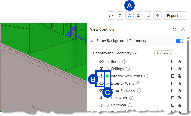
Wall function may also be verified after the Background Geometry has been imported into your study by using the  View Controls in the 3D Model Preview.
In the View Controls panel, ensure that the
 visibility toggles for the Interior Wall Items and Exterior Walls categories are turned on
 .png) .
.Click the category’s
 color selector.
Make sure to set contrasting colors for each category to easily identify them.
Exterior walls
 are displayed with diagonal lines while Interior walls
  are plain colored.
In Revit
To visually verify the Function of the walls during project setup, apply the ACP-Plan view template to a working Plan view. This view template contains a view filter which highlights in red all walls with the Function parameter set to Exterior. Interior walls will not be highlighted.
Resolving the Issue
Any incorrectly set wall Function in your Revit model must be resolved. Here are some of the ways you can resolve this issue. There are a few workarounds which give ACP more flexibility in how it detects and penetrates walls in projects where wall functions are misassigned.
Placing May Route Boxes .png) in your Revit model allows conduits to penetrate non-structural obstructions.
in your Revit model allows conduits to penetrate non-structural obstructions.
When only some Interior walls have their Function parameter incorrectly set to Exterior within the model, May Route Boxes may be used to manually create the few penetrations needed.
The Automatically detect exterior walls setting of the Routing Through Walls design rule must be toggled on
.png) .
.
Placing Keep Out Boxes  in your Revit model creates obstructions which prevent conduit from routing through.
When the Function parameter of many or all Interior walls are set to Exterior:
The Automatically detect exterior walls setting of the Routing Through Walls design rule must be toggled off
.png) .
.Keep Out Boxes may be placed outside these walls to manually obstruct the area.
When the Function parameter of some Exterior walls is incorrectly set to Interior, but majority of the walls are set correctly:
The Automatically detect exterior walls setting of the Routing Through Walls design rule must be toggled on
.Place Keep Out Boxes on the outside of the few walls with incorrectly set wall Function.
Scope Boxes placed within the model may be used as a Scope to control where design rules apply within a project.
When the Function parameter of many or all interior walls are set to Exterior within the project, use Scope Boxes to limit the scope of where the Route Through Walls design rule is applied. Follow the steps below:
Create a Scope Box offset by a foot or two inside the exterior walls.
Enter a descriptive name for the Scope Box to easily identify it in the next step.
Assign that Scope Box as the Scope for the Route Through Walls design rule.
Toggle off
the Automatically detect exterior walls setting for that design rule.If multiple scope boxes are required to cover the building footprint, create additional scope boxes and design rules as needed.
Correcting the Function property of the problematic wall(s) within the Revit link will also resolve the issue and ensure correct behavior.
However, this option is only viable if:
You have ownership of a copy of the linked file.
You are not likely to receive updated copies of the linked file.
If you do receive an updated copy, it is likely you will need to adjust the Function property for several walls again, or the issue with reemerge.
Supportability Issues
As ACP analyzes the site to determine possible conduit routes, it also looks for supportable surfaces within the model. Supportable surfaces in the Revit model are those where the specified supports in the Supports design rule may be installed.
The most common supports ACP uses are overhead supports such as trapeze hangers which are hung from the floor or roof above. When these overhead supportable surfaces are not present in the ACP-Import view, ACP will look for alternative support methods. If none are found, ACP will either find an alternative path, which may result in odd routing, or fail to route altogether.
What it may look like in ACP
Unrouted Runs
When reviewing the Unrouted Runs, the Explored Space highlights areas which ACP explored while finding conduit routes. If ACP explored the entire site but wasn’t able to find a suitable route or termination for the conduit run, the explored space may show:
Large areas of explored space with noticeable gaps or pinch points. (Sometimes)
Similar to what is seen with Excessive Geometry
Limited explored space that is close to the source or destination.
Similar to what you may see with Overfilled Electrical Equipment. (More Frequent)
Reviewing the ACP model
There are multiple supportability issues which may cause Unrouted Runs. These issues must be identified and resolved in your Revit model.
Below is a list of possible issues in your Revit model which impact supportability:
Missing supportable surfaces
Odd openings in floors
Floor/Roof structures missing entirely
These may have been accidentally turned off in a linked model while hiding other elements.
Miscategorized Support Elements
Elements in the linked Structural or Architectural models in the wrong category. For example,
Ceilings modeled as structural elements
Roof modeled as floor in one link, and a roof in another
Obstructions blocking supportable surfaces
Mechanical or structural elements modeled so large that they prevent ACP from seeing a surface as supportable
Elements placed outside of the building without overhead supportable surfaces
Elements placed on a roof, such as Mechanical Equipment disconnects
Elements placed at some distance from the building, such as Exterior Lights
Background Geometry View Controls
Prior to generating solutions, you may review your imported Background geometry in the 3D Model Preview. Using the View Controls, you can review your Background geometry for any supportability issue so you can make the necessary adjustments in your Revit model before re-importing it into your study.
Follow the steps below.
In the View Controls panel, turn off the visibility for all of the category groups except for Floor Surfaces and Roofs.
Look for holes or gaps on the floors.
Turn on the visibility for one category group at a time.
Look for obstructions near floors and roofs such as fake ceilings, large ducts, or masses placed to claim space.
Look for elements which may have been intended to represent supportable surfaces.
Only elements categorized as Floors or Roofs are identified in ACP as overhead supportable surfaces.
Supportability Visualizations
ACP looks for supportable volumes in the model while generating solutions. All supportable volumes found are visualized in the generated solutions.
To view the supportable volumes found by ACP:
In the View Controls panel, expand the Visualizations section.
Turn on the Overhead visibility under Supportable Volumes.
Pro Tip:
For a better view of the Supportable Volumes, turn off the visibility for other Visualization category groups and cut through the model by using Section Planes.
Supportable Volumes are visualized like empty boxes: the sides bound the volume that is supportable. Because supportable volumes are structured as such, the best way to review them is by sectioning them to see the sides bounding it.
Overhead Supportable Volumes start from a supportable surface (Floor or roof above) and extend down until it encounters an obstruction which blocks supportability. This obstruction may be a ceiling, a large duct, or a large mass.
While the volume appears hollow when cut, you can verify that it is supportable by looking at the faces of the volume (typically the walls of a room) which will be colored until the horizontal obstruction is hit.
Resolving the Issue
Supportable elements are typically found within the Architectural and/or Structural linked models, which are not typically modifiable for Electrical Teams. Because the supportability issues can’t be resolved by modifying the linked models, resolving these issues involves more manual corrections such as:
Turning off the visibility of any miscategorized support elements, or obstructions blocking supportability
Manually modeling supportable elements such as floors or roofs over areas of the model missing supportability
Areas with holes and gaps
Over rooftops which need supportability to route to destinations
Temporarily moving elements located outside but close to the building so that they are placed inside the building.
Such as J-boxes mounted on the exterior face of the building.
Routing issues for elements placed like this are caused by a combination of lack of supportability and the route being blocked by the Exterior wall.
To resolve this,
Create a copy of the Electrical Fixture family by saving it as a new file.
Edit the copied Electrical Fixture family to move its Electrical Connector to the opposite face to allow the conduit to attach to the bottom face.
Load the edited family back into the Revit project.
Replace the family of the problematic Electrical Fixture with the edited family.
Place a May Route Box under the new Electrical Fixture family to allow ACP to penetrate the roof below.
Or,
Replace the Electrical Fixture with a family in the category of Electrical Equipment with a Part Type of Other.
Electrical Equipment families have clash free boxes which extend 6’ down, penetrating the roof below.
Unexpected floor penetrations
In addition to providing supportability for the conduits below, floors act as obstructions which restrict where conduits can travel vertically within the site. When there’s a hole or a gap on the floor leading to what seems like a large available space, regardless if routing is realistically permitted or efficient in that space, ACP will likely route through it. This is especially crucial on the Ground Level of any building where ACP treats the space underground as a large available space.
There are three main causes of these unexpected floor penetrations:
The ACP_E_Target_Bottom_Face parameter is turned on.
When turned on, this parameter enables the ACP Surface Connector and Clash-free Box at the bottom of any Panelboard, Other Panel, or Switchboard.
Because the bottom Clash-Free Box of Electrical Equipment (except Transformers) extends 6’ down, conduit may penetrate the floor and route below it instead of overhead on the same level.
To prevent routing below the floor where the Electrical Equipment is placed, this parameter should be turned off.
A May Route Box is misplaced within a floor or slab.
May Route Boxes allow ACP to penetrate any non-structural obstruction.
The floor geometry has holes modeled directly into it .
This happens most frequently in remodels or TI projects where part of a model may be have been created separately.
It may also happen as a result of miscategorized floor structures which are accidently turned off in the ACP-Import View.
What it may look like in ACP
Odd routing
Unexpected floor penetrations don’t usually block routing. However, they are likely to cause odd or unexpected routes which may appear as the following:
Instead of routing within the level where the Source or Destination is placed, conduit may penetrate down through a floor and route overhead within the lower level.
Route outside of the building as if routing underground.
ACP does not currently support true underground routing. Any underground routing in generated solutions is considered accidental.
Conduits may terminate on the bottom face of the equipment even when the top face was the target.
Reviewing the model
Unexpected floor penetrations may be identified in your model either in ACP or Revit.
Turn off the visibility for all categories/category groups except for Floors and/or Generic Models.
Review the model for possibly misplaced May Route Boxes, or holes in the floor structures.
Resolving the Issue
To avoid odd routing due to unexpected floor penetrations,
Add geometry to the Revit model to block holes in the floor structure.
This can be done with Keep Out Boxes or Floor elements.
If the Floor structure has a lot of holes, it may make more sense to do the following:
Turn off the Floor’s visibility within the ACP-Import view.
Manually model a new floor structure across that level of the site.
Ensure the ACP_E_Target_Bottom_Face parameter is turned off at least for all Electrical Equipment on the Ground Level.
This prevents accidental underground routing.