The Electrical Model is one of the Design Inputs of a Study used to generate solutions in ACP. In generating solutions, the Electrical model:
Identifies the location, size, and other properties of the enabled Electrical Equipment and Electrical Fixtures which ACP will use as sources and/or destinations for the conduit routing, as well as various elements used for constraining routes.
The Electrical model consists of the following elements in your Revit model:
All enabled Electrical Equipment and Electrical Fixtures
Guidance Boxes and Guidance Spaces
Scoping elements
Spaces (Including Area Class and Preferred Space data)
Scope Boxes
 Existing conduit runs in the Revit project are imported as part of the Background geometry.
Below are the common issues found in the Electrical model which may cause unrouted runs, odd routing, solution failure, or other issues when generating solutions.
Issue | Failed Solution/Other | Unrouted Runs | Odd Routing |
|---|---|---|---|
✘ | |||
✘ | |||
✘ | ✘ | ✘ | |
✘ | ✘ |
Geometry in families blocking routing
Because Electrical Equipment and Electrical Fixtures are loadable families, they can be modeled in a number of different ways. These loadable families may be created internally, provided as part of third-party workflows, downloaded from manufacturers, or copied directly from the Electrical Engineer’s project. How ACP terminates conduit to these electrical elements depends on their configuration.
ACP Surface Connectors are ACP-generated connectors where conduits terminate on electrical elements used as Sources and Destinations of a raceway. The faces where ACP Surface Connectors attach depend on the element’s Category (Electrical Fixtures or Electrical Equipment), Part Type, and the placement of Revit’s Electrical Connector within the family.
Nesting existing families within another may interfere with the ACP Surface Connectors depending on the nested family’s category and its Shared setting.
The categories of the nested and host families are not required to match in Revit, affecting the visibility of that nested family within the Revit project. For example, a Generic Model Box may be nested within an Electrical Equipment family.
Nested families may be set as Shared which allows Revit to treat them as independent elements for scheduling and tagging, while still being hosted within the parent family. This can be helpful when creating an in-depth Bill of Materials for the Revit project.
For ACP, Shared non-electrical families nested within Electrical Fixtures or Electrical Equipment families may be interpreted as obstructions, blocking ACP Surface Connectors which causes unrouted runs.
What it may look like in ACP
Unrouted Runs
In the 3D Solution Viewer, the Unrouted Runs feature within the Placement Considerations panel lists all the raceways that ACP wasn’t able to route. In addition to that, it shows the Explored Space which highlights in blue all the areas that ACP explored while trying to route the raceway you select from the list.
If the cause of the Unrouted Run is nested families blocking ACP Surface Connectors, the Explored Space may appear as:
A very small box starting from the top of the physical panel, and ending abruptly at an obstruction just a few inches above.
No visible explored space.
Reviewing the Revit model
Some objects found to cause issues when nested within Electrical Fixtures and Electrical Equipment families include the following:
Model text
Clearances
Objects used as clearances but aren’t in a sub-category containing the word Clearance
Clearances in categories other than Electrical Equipment or Electrical Fixtures
Pull boxes/Gutters
Structural supports (struts, stands, etc.)
Support rods
Simple extrusions for structure with a Detail Level of Coarse or Medium
Resolving the Issue
The workarounds to prevent nested families from block termination points are as follows:
ACP imports all geometry at a Fine detail level, regardless of their setting in the ACP-Import view where ACP imports geometry from. The exceptions to this are Electrical Equipment and Electrical Fixtures which are imported at a Medium detail level.
To hide the problematic nested family within Electrical Equipment and Electrical Fixtures, set the nested family’s Detail Level to Medium.
You can also completely remove it from the host family if doing so will not interfere with other processes.
WARNING: This requires a high level of family editing expertise and planning to ensure all needed elements are still available for other purposes.
If you require additional help with this process, reach out to support@augmenta.ai.
A placeholder Source/Destination may be used to ensure that ACP is able to route to the location of the Source/Destination even if the conduit doesn’t directly terminate on it.
Follow the steps below:
Place a pull box/gutter above or around the Source/Destination with nested families blocking termination paths.
The pull box/gutter should be categorized as either Electrical Equipment or Electrical Fixture, and identified via the Panel Name or the ACP_E_Fixture_ID parameter.
To easily identify a placeholder electrical element and avoid duplication, add a placeholder identifier character to its Panel Name/ACP_E_Fixture_ID. For example. H1_g where g stands for gutter.
Turn on the ACP_C_Enabled parameter for the pull box/gutter.
Turn off the ACP_C_Enabled parameter for the original Source/Destination.
In the generated solutions, conduit runs will terminate on the placeholder Source/Destination. After the solution has been exported into your Revit model, you’ll have to manually connect the conduit run to the original Source/Destination.
Overfilled Electrical Equipment
Conduit specifications for each raceway in the Conduit Schedule are determined by the Feeder ID which is referenced from the Feeder Schedule where the specifications (Conduit Size and number of Parallel Runs) are defined. These specifications, combined with the actual routable surface of any piece of equipment, enable ACP to determine the number of conduits which can realistically terminate on the electrical element used as Source/Destination.
For Electrical Equipment (except Transformers), only the top and/or bottom surfaces are routable. If the Electrical Equipment is overfilled such that its routable surface isn’t enough for all the conduits that must connect to it, one or more raceways may fail to route.
What it may look like in ACP
Unrouted Runs
In the 3D Solution Viewer, the Unrouted Runs feature within the Placement Considerations panel lists all the raceways that ACP wasn’t able to route. In addition to that, it shows the Explored Space which highlights in blue all the areas that ACP explored while trying to route the raceway you select from the list.
If overfilled Electrical Equipment is the cause of the Unrouted Run(s) , the Explored Space may appear as:
A very small box starting from the top of the physical panel, and ending abruptly at an obstruction just a few inches above.
No visible explored space.
Reviewing the Panel Fill in ACP
Determining if overfilled Electrical Equipment is the cause of the Unrouted Runs can be challenging as there’s no definitive test or tool to diagnose it. The best way to infer if this particular issue is the cause of the unrouted run may be the following:
Compare the dimensions of the total routable surface of the Electrical Equipment with the total area required to accommodate all the conduits that must route to it as indicated in the Conduit Schedule, considering conduit specifications.
Test if the unrouted run resolves by applying the workaround in the next section.
Resolving the Issue
A placeholder Source/Destination may be used to ensure that ACP is able to route to the location of the Electrical Equipment even if the conduit doesn’t directly terminate on it.
Follow the steps below:
Place a pull box/gutter above or around the Electrical Equipment.
The pull box/gutter is categorized as either Electrical Equipment or Electrical Fixture, and identified via the Panel Name or the ACP_E_Fixture_ID parameter.
To easily identify a placeholder electrical element and avoid duplication, add a placeholder identifier character to its Panel Name/ACP_E_Fixture_ID. For example. H1_g where g stands for gutter.
Turn on the ACP_C_Enabled parameter for the pull box/gutter.
Turn off the ACP_C_Enabled parameter for the original Electrical Equipment.
Incorrect Electrical Element classification
Because Electrical Equipment and Electrical Fixtures are loadable families, they can be modeled in a number of different ways. These loadable families may be created internally, provided as part of third-party workflows, downloaded from manufacturers, or copied directly from the Electrical Engineer’s project. Regardless of the origin, the family’s Category and Part Type are crucial as these determine how ACP views, processes, and ultimately routes to the elements when used as Sources/Destinations.
Below are some common Electrical Element classification issues:
A Source/Destination modeled as a placeholder element such as a Mass or Generic Model
Only elements categorized as Electrical Equipment or Electrical Fixtures are recognized as potential Sources and Destinations in ACP.
If you’re using a mass or a generic model as a placeholder for a Source or Destination, ACP will only treat it as an obstruction.
Electrical Equipment Part Types
The Electrical Equipment Part Type determines the faces of the element that have ACP Surface Connectors and Clash-Free boxes which significantly impact routing. When the Part Type is incorrectly set, ACP may not be able to route to the element correctly or, in some cases, completely fail to route.
J-boxes modeled as conduit fitting
Some workflows may include J-boxes as part of the conduit system to allow for automated placement and connection to the Conduit Run.
ACP does not currently support any elements outside of the Electrical Equipment & Electrical Fixtures categories to be used as Sources and Destinations. Any J-box Source or Destination must be placed using a family in the Electrical Fixtures category.
What it may look like in ACP
 Prior to solution generation
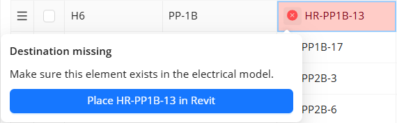
The ACP Conduit Schedule connects with the live Active Revit project to ensure that all specified Sources and Destinations are accounted for within the Revit model. When ACP is unable to locate a specified Source or Destination within the Revit model, ACP will return the Source/Destination Missing error.
This error may indicate that the Category of the element placed as a Source or Destination in your Revit model may be incorrect.
Odd Routing
When the Category of the Electrical Equipment is set correctly but its Part Type is incorrect, ACP will connect conduit to incorrect faces of the element, resulting in odd routing. For example,
A family is placed to represent a Transformer but its part type is incorrectly set to Switchboard, ACP will treat the Transformer as a Switchboard. Instead of terminating on the sides, conduit will terminate at the top of bottom of the transformer.
Reviewing the Model
In ACP
While Part Type impacts how an electrical element functions within the Revit project (including default parameters), it’s not a schedulable parameter, making it difficult to track in Revit. In ACP, you can check the Part Type of the electrical element after importing the Electrical model into your ACP study.
Follow the steps below.
In the Design Inputs sub-tab of your ACP study, import the Electrical model.
A timestamp under the Import Active Revit Project button will appear when the import is complete.
In the 3D Model Preview, click the View Controls button.
Turn off the visibility of all category groups except Electrical Fixtures, Electrical Equipment, and Surface Connectors.
Assign contrasting colors to the Electrical Fixtures and Electrical Equipment to easily differentiate them.
If you’re unable to locate the element:
It may be miscategorized in your Revit model.
Its ACP_C_Enabled parameter may be disabled.
Check for Surface Connectors on the Electrical Equipment.
If the Surface Connectors are in unexpected locations:
The Part Type of the element may be incorrect.
The orientation when the family was built may be rotated or set incorrectly.
In Revit
Electrical Fixture and Electrical Equipment schedules are extremely helpful in identifying elements which appear in the Revit model but aren’t found when entered as a Source or Destination in the Conduit Schedule of an ACP study.
See Utilizing Schedules for troubleshooting for more information.
Resolving the Issue
ACP needs both the Category and Part Type to be correct in order to route correctly to any electrical element. Any incorrect classification of electrical elements must be resolved. You can do either of the following:
Edit the family instance and update the Category and Part Type.
Replace the problematic element with another element from a correctly configured family.
Element placement Issues
Electrical Equipment and Electrical Fixtures used as Sources and Destinations must be accessible in some way for ACP to successfully route to and from them.
Primary power sources of a building are placed early on in the project by the Electrical Engineering team while additional electrical fixtures and equipment required to distribute power across the site, such as home-run junction boxes, disconnect switches, and pull boxes, are usually placed by the Construction team later. In Revit, placing the additional electrical elements is most often done in a plan view or a cropped 3D view. Because these views do not always show all surrounding elements, the additional electrical elements can potentially be placed in locations where viable ACP routing paths are blocked or unusual.
Electrical elements may be accidentally, partially or fully, embedded in an obstruction such as structural column, beam, wall, or duct.
Both Electrical Equipment and Electrical Fixtures have Clash-Free boxes to help make them easier to reach in case of accidental placement issues. However, they may still be blocked if they’re placed within structural elements which Clash-Free Boxes don’t penetrate, or if they’re placed too far within an obstruction for ACP to reach.
What it may look like in ACP
Unrouted Runs
In the 3D Solution Viewer, the Unrouted Runs feature within the Placement Considerations panel lists all the raceways that ACP wasn’t able to route. In addition to that, it shows the Explored Space which highlights in blue all the areas that ACP explored while trying to route the raceway you select from the list.
If the Unrouted Run(s) is caused by the Source/Destination being embedded fully or partially in another element, the Explored Space may appear as:
A shaded volume completely contained within the object where a Source/Destination is embedded.
The Explored Space ends where the object intersects with another.
For example, if the Source/Destination is embedded within a floor which is intersected by a wall, the Explored Space will end where the wall intersects.
A shaded volume encompassing the entire site.
No Explored Space is visible in the view.
Odd routing
When elements are placed in unusual locations, such as being mounted much higher than the rack, it may cause strange turns in the rack, odd elevation changes, or inconsistent penetrations as ACP navigates around the geometry to reach the element.
Reviewing the model
In ACP
Element placement issues in your Revit model can be reviewed in ACP with the use of View Controls and Section Planes.
View Controls control the visibility settings and section cut behavior of each category group.
Section Planes show the cross-section of the model to see how elements are modeled together.
In Revit
In your Revit project, you can spot any Electrical Equipment and Electrical Fixtures embedded in other geometry or placed in unusual locations in many ways. This includes the following:
Utilize Electrical Equipment and Electrical Fixtures schedules for troubleshooting.
Follow the Reviewing the Revit Model instructions to effectively explore the Revit model using the Selection Box tool.
Use a duplicate of the ACP-Import view while exploring or troubleshooting your Revit model so you can freely adjust settings without potentially breaking necessary settings in the view.
Resolving the Issue
The best way to avoid routing issues caused by element placement is to ensure that Sources and Destinations aren’t embedded in other geometry or placed in unusual locations. Move the elements out of any geometry they’re embedded in and ensure they’re placed in accessible locations.
If moving the element is not an option, you may use a May Route Box to create the necessary penetration, making it accessible for conduit routing.
For example, placing a May Route Box over a duct makes its interior accessible to ACP for routing. Because a duct is hollow, ACP will see its interior as available space and route conduit within it.