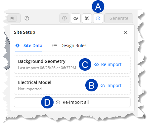
The Site Data has two components: Background Geometry and Electrical Model. The Background Geometry
Import Site Data
 To import Site Data from the ACP-Import view of your Revit project by following the steps below.
Click the
 Site Setup button.
In the dropdown Site Setup panel, click the
 Import button for the Background Geometry and Electrical Model.
When the Site Data has been imported, the button will change into
 Re-import and the timestamp of the last import will be displayed.
 To import both site data at the same time, click the
 Import all / Re-import all button.
Once ACP finishes importing and processing the site data, the imported geometry will be displayed in the 3D Model Viewer.
The same ACP-Import view in your Revit project project may be used for either an Automatic Study or Interactive Study. Follow the same process for setting up your ACP-Import view for both to minimize the geometry ACP has to calculate, keep your view readable, and minimize unnecessary clashes with non-coordination geometry.
Prepare the Site for drawing
For most raceways, the Source and Destination are on the same floor, making it practical to route floor by floor before connecting with risers. Set up the floors in the site to view the floor’s planes and/or switch between isolated floor views when drawing the raceway routes. Setting up the floors also allows you to specify the elevation to snap to when drawing.
Each floor has three planes:
Top Plane - The upper boundary of the floor. When the floor is selected, all geometry above this elevation is cropped from the view.
Work Plane - The default elevation where segments are drawn, similar to the Preferred Height.
Bottom Plane - The lower boundary of the floor. When the floor is selected, all geometry below this elevation is cropped from the view.
 Set up floors
Follow the steps below to set up floors in your site.
Modify the view so the floors are visible.
Use a Section Plane to create a cross-section of the site so the floors are visible.
Or use the View Controls to Hide
.png) the Exterior Walls in your site or make them Transparent
the Exterior Walls in your site or make them Transparent .png) .
.
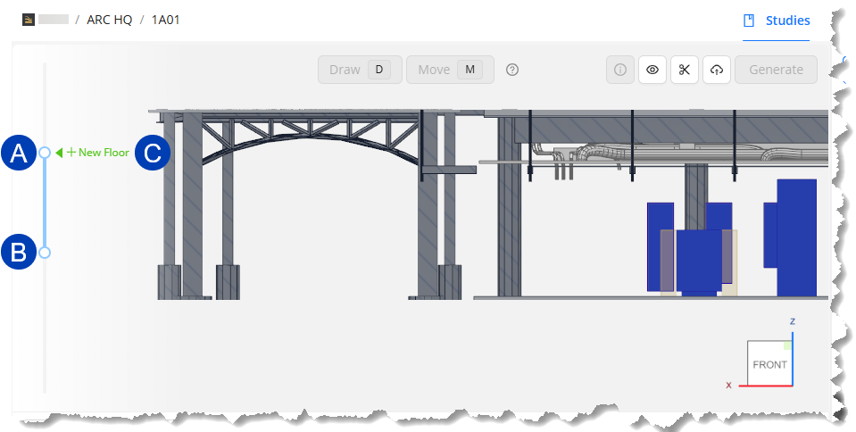
Click and drag the
 top and
  bottom grips of the Section Slider so the model is cut to roughly the center of the slab of the floor above and the slab of the current floor.
Click the
 New Floor button which appears next to the Section Slider.
The first floor you create will be named Floor 1 by default. The floor number will increase as you create more floors.
In the Edit Floor pane that appears, you can configure the height of the different planes in the floor.
To set the Work Plane elevation, you can either manually specify the elevation or Sample height from the 3D view.
.png) In the Edit Floor pane, enter the elevation in the
In the Edit Floor pane, enter the elevation in the  Work Plane textbox or use the up and down arrows to specify the height.
The Work Plane’s
 distances from the Top Plane and the Bottom Plane are displayed below it. The distances are updated as you adjust the Work Plane’s elevation.
.png) The Work Plane may be set to the same elevation as Surface Connector Targets (the purple arrows, such as
The Work Plane may be set to the same elevation as Surface Connector Targets (the purple arrows, such as  , attached to a Source/Destination’s ACP Surface Connector) in the site. Waypoints (such as
  ) and segments (such as
  ) may also be sampled for Work Plane elevation if they’re already placed in the site.
Follow the steps below.
In the Edit Floor plane, click the
 Sample elevation button beside the Work Plane textbox.
A
 banner will appear at the bottom: Select a segment, waypoint, or surface connector to sample its height. Press Esc to cancel.
Select the segment, waypoint, or target you’d like to reference as the Work Plane elevation.
The Work Plane elevation will be the same as the selected element.
(Optional) In the Edit Floor pane, change the Name of the floor.
To start creating another floor, click and drag either the top or bottom grip so the New Floor button reappears.
Repeat the steps to create each floor in the building.
.png) Set Conduit Spacing
Set Conduit Spacing
Conduit Spacing controls the minimum spacing between conduits on a rack. This affects the size of the Rack Preview.
Follow the steps below to set the minimum spacing between conduits in a rack.
Click the
 Site Setup button.
In the Site Setup panel, navigate to the
 Design Rules tab.
Enter the
 Minimum horizontal spacing and
  Minimum vertical spacing.
Next Steps
Once all electrical elements have been placed and scheduled, you may start creating raceway routes. Refer to the next article.