The 3D Model Viewer in ACP provides an interactive environment for exploring routing solutions in detail. Users can review conduit paths, analyze supportable volumes, and inspect potential issues in the Solution.
This article discusses the Navigation Controls and the Features of the 3D Solution Viewer.
Navigation Controls
The 3D Model Viewer supports intuitive movement using a combination of on-screen, and mouse controls which allow users to move within the space, orbit around specific points, and pan across views. This section outlines the different navigation controls in the 3D Model Viewer.
Move controls
Move controls allow users to shift the camera position in any direction, changing the viewpoint rather than rotating around a fixed point.
Mouse Control | Description (Click the dropdown |
|---|---|
Right-click and drag |
|
Scroll wheel |
|
.gif)
Orbit control
Orbit control allows you to rotate the camera around a fixed point: up, down, left, or right, changing the viewing angle without moving the camera’s position.
Mouse Control | Description (Click the dropdown |
|---|---|
Left-click and drag |
|
View controls
The View Cube on the bottom-left corner of the 3D Solution Viewer allows you to easily switch planes on the 3D model by clicking on or dragging its labeled faces, edges, and corners.
Action | Description (Click the dropdown |
|---|---|
Click |
Clicking the same part again zooms out to the extents of the model while keeping the same orientation. |
Left-click and drag |
|
Features
The features of the 3D Solution Viewer let users easily review the solution and compare it with others, helping users determine the best solution for their Revit project.
.png)
 Back button - Close the 3D Solution Viewer and return to the Solutions list.
 Solution color - The default color assigned to any solution when opened in the 3D Solution Viewer.
This color may be changed to your preferred color as you review the solution in the viewer.
 Solutions dropdown - Replace the current solution with another from the same or a different study.
 Share solution - Copy a shareable URL of the solution.
 Compare solutions - Open two solutions in the 3D Solution Viewer for a side-by-side routing comparison.
 Solution Details - View data and statistics of the solution.
 Placement Considerations - Open the panel showing unrouted runs and missing parts.
 View Controls - Configure visibility of different elements of the model.
 Section Planes - Cut through the 3D model to show it’s cross-section.
 Bookmark - Save specific points in the model for later review.
 Issues - Displays errors and warnings related to the process of generating the solution.
 Most warnings at this stage are specific to ACP developers and may be ignored by users.
 Export - Export the conduit solution solution into a Revit project or a Conduit Schedule as a .xls file.
Refer to the Exporting a Solution to a Revit project article for a step-by-step guide.
 Section slider - Drag the top and bottom points to create a vertical section of the model.
Compare solutions
The Compare solutions mode simultaneously opens any two solutions within the ACP Project in the 3D Solution Viewer, allowing for a visual comparison of the two using different colors to represent each one. Other features are also updated to support the comparison.
.png)
Below are the controls for comparing solutions in the 3D Solution Viewer.
 Primary Solution dropdown - Change the Primary Solution in the comparison.
 Secondary Solution dropdown - Select the Secondary Solution in the comparison.
 Secondary Solution color - Change the temporary color assigned to the secondary solution.
 Changing this color does not change the corresponding study’s assigned color.
 Swap solutions - Swap the primary and secondary solutions.
 In Compare solutions mode, the Primary Solution takes precedence in the display and features.
This means the Electrical Model and Background Geometry in the Primary Solution are used in the 3D Solution Viewer, and full functions of the 3D Solution Viewer features may be used on it.
 Share solutions comparison - Copy a shareable URL of the comparison of the two solutions.
 Exit Compare solutions mode - Exit the Compare solutions mode and show the Primary Solution only.
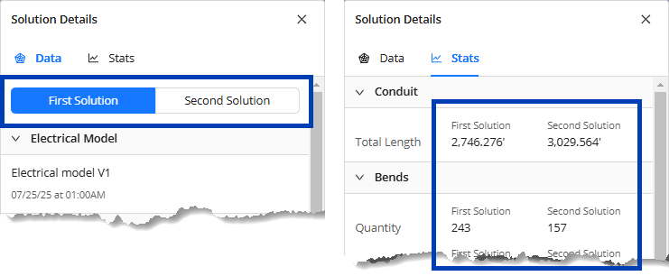
 Solution Details - Compares the data and statistics of the two solutions.
Data tab - Shows the data of the two solutions being compared in separate tabs.
Stats tab - Displays separate columns for the Primary Solution (First Solution) and the Secondary Solution (Second Solution) to compare their stats.
 Placement Considerations - Shows the unrouted runs and missing parts of the Primary Solution.
 Swap the solutions to show the Secondary Solution’s instead.
 View Controls
In the Electrical group, show
.png) or hide
or hide .png) the Primary Solution (Solution 1) and/or the Secondary Solution (Solution 2).
the Primary Solution (Solution 1) and/or the Secondary Solution (Solution 2)..png)
In the Bookmarks group, show
.png) or hide
or hide .png) the bookmarks in the Primary Solution (First Solution) and/or the Secondary Solution (Second Solution).
the bookmarks in the Primary Solution (First Solution) and/or the Secondary Solution (Second Solution).Bookmarks in the
 Primary Solution are clearly shown in the model while those in the
  Secondary Solution are slightly transparent.
Bookmark - Divided into two tabs to separately show the list of bookmark(s) in the two solutions.
The bookmarks for the Secondary Solution are view only.
Swap the solutions to fully control bookmarks in the Secondary Solution.
.png)
Solution Details
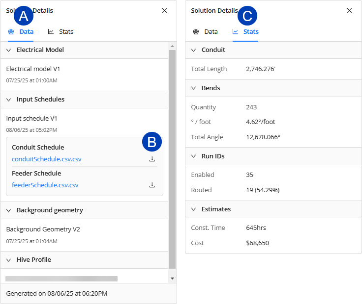 The Solution Details panel contain all information related to the solution. It’s divided into two tabs:
 Data tab - Shows the Electrical Model, Input Schedules, and Background geometry used in the Study from which the solution was generated. It also shows the date and time when the solution was generated.
 Download button - Download any of the Input Schedules as a CSV file.
 Stats tab - Presents information related to the results of the solution generation and the solution itself. The data in this tab are as follows:
 These data are also displayed in the Solutions table.
 Conduit - Displays information regarding the conduit itself.
Total Length - Displays the total conduit length in feet.
Bends - Shows the information specific to the bends or elbows within the solution.
Quantity - The total number of bends included in the solution.
° / foot - Specifies the average bend angle across all conduit runs. This is calculated by dividing the Total Angle by the length of all straight conduits.
Total Angle - The cumulative sum of all bends’ angles within the solution.
Run IDs - Displays information regarding elements specified in the Conduit Schedule, and Revit project to be used for routing.
Enabled - The number of Revit elements enabled and specified in the conduit schedule for the Study.
Routed - Displays the number of enabled runs which were successfully routed. A percentage based on the total number enabled and how many were successfully routed is also displayed.
Estimates
Const. Time - A rough estimate of the installation time required for the solution.
Cost - A rough estimate of the cost associated with the solution's implementation.
 Estimates are intended for comparing solutions only and should not be used to determine actual construction amounts, as values can vary by region.
Placement Considerations
The Placement Considerations panel provides tools to review routing issues within the solution. It’s divided into two tabs: Unrouted Runs and Parts.
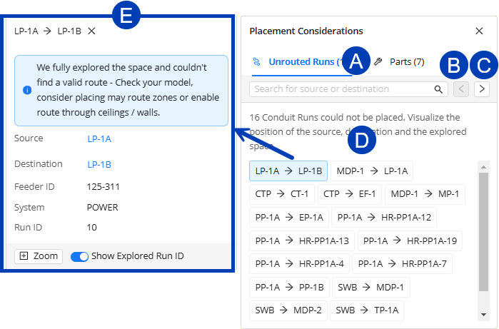 Conduit runs which ACP was not able to route are listed in the Unrouted Runs tab in Source-Destination format. Exploring unrouted conduit runs from the Placement Considerations panel allows users to quickly find it in the model, providing visual context for why ACP wasn’t able to fully route the Conduit Run.
Here are the functions within the Unrouted Runs tab.
 Search - Shows unrouted run(s) with either source or destination matching the entered name of the Electrical Equipment (Panel Name) or Electrical Fixtures (ACP_E_Fixture_ID).
  Previous conduit run - Selects the previous unrouted run.
 Next conduit run - Selects the next unrouted run.
 Unrouted runs list - Displays unrouted runs in Source-Destination format.
 Select any one to zoom in to its Source, which is displayed as a target sphere, and to display the Unrouted run information panel.
 Unrouted run information panel - Displays details of the unrouted run which were derived from the Conduit Schedule.
Click the Source or Destination to zoom in to its location where it’s displayed as a target sphere.
.png) The Parts tab lists the parts that ACP was unable to place within the conduit run, shown as an orange rectangle. These unknown parts will be exported with the solution when it is exported into the Revit project as Generic Model families, so they may be located within the model and manually fixed.
The Parts tab lists the parts that ACP was unable to place within the conduit run, shown as an orange rectangle. These unknown parts will be exported with the solution when it is exported into the Revit project as Generic Model families, so they may be located within the model and manually fixed.
The controls within the Parts tab are as follows..png)
 Search - Shows the parts with names matching the entered text.
 Previous part - Navigate to the previous part.
 Next part - Navigate to the next part.
 Parts list - Displays parts that ACP wasn’t able to place.
 Select any one to zoom in to its location and to display the Part information panel.
 Part information panel - Shows all the Part type(s) tried to build the conduit run between the Source(s) and Destination(s).
View Controls
.png) View Controls allow users to control the visibility of different elements of the model, making it easier to focus on specific areas without other parts obstructing the view. The View Controls are organized into three sections: Show Background Geometry, Visualizations, and Electrical. The model can also be configured to show or hide Bookmarks via the View Controls.
View Controls allow users to control the visibility of different elements of the model, making it easier to focus on specific areas without other parts obstructing the view. The View Controls are organized into three sections: Show Background Geometry, Visualizations, and Electrical. The model can also be configured to show or hide Bookmarks via the View Controls.
 Reset view controls - Restores the default view controls settings.
 Expand/Collapse toggle - Expands or collapses the view control group.
 Section toggle - Show
 .png) or hide
or hide .png) all View Controls within the group.
all View Controls within the group.  View control information - Lists the elements/categories controlled by the View Control in a tooltip.
 Visibility toggle - Show
 .png) or hide
or hide .png) the parts of the model controlled by the corresponding View Control.
the parts of the model controlled by the corresponding View Control. Color Selector - Change the color of the parts of the model controlled by the corresponding View Control.
 Transparency toggle - Controls if the corresponding elements/categories are solid
 .png) or transparent
or transparent .png) .
. Section toggle - If turned on
  , the corresponding category will be cut off by section planes or the Section Slider. If turned off
 .png) , the category will be excluded from the cut.
, the category will be excluded from the cut.
Show Background Geometry
.png) In the Show Background Geometry section, each view control is a group of categories in Revit which are imported into the ACP study as part of the Background Geometry. These Revit categories are grouped together in ACP by common category types.
In the Show Background Geometry section, each view control is a group of categories in Revit which are imported into the ACP study as part of the Background Geometry. These Revit categories are grouped together in ACP by common category types.
In addition to controlling the visibility of these Revit category groups in the 3D Solution Viewer, users can choose a different Background Geometry using the dropdown. Any existing Background Geometry in the ACP project can be used.
Visualizations
The Visualizations view control group contains visibility settings for ACP-specific geometry. Enabling these view controls shows in the model how certain areas were treated in generating the conduit route.
Below are the Visualizations view controls and their descriptions:
View Control | Description |
|---|---|
Routing Boxes | Shows the Guidance Boxes placed in the Revit project, which are then imported into the ACP study as part of the Electrical Model. The different Guidance Boxes are as follows: (Click the down arrow for more details)
|
Preferred Spaces | When multiple routes are possible, Preferred Space tells ACP to choose a route that runs through this space.
|
Keep out Spaces | Prevents ACP conduits from routing within the volume of the specific Revit Spaces.
|
Off-Axis Areas | Shows the off-axis mass(es) in the model, indicating where ACP should deviate from the standard orientation relative to Project North when creating conduit routes. |
Surface Connectors | Visualizes the Surface Connectors on the face(s) of each electrical element where conduits can be routed. For more information, refer to ACP Surface Connectors. |
Supportable Volumes | Helps users analyze if certain areas can be used for placing support elements such as trapeze and wall plate. Click the down arrow for more details about supportability visualization.
|
.png) Shows the supportable volume from the floor above until an obstruction, such as a ceiling (red
Shows the supportable volume from the floor above until an obstruction, such as a ceiling (red  ), floor (yellow
  ), or roof (green
  ), is encountered. This is best viewed from a cross-section of a side, front, or back view where you can see the faces of the volume.
 ,
,  ,
,  , and
, and  are all supportable. It’s helpful to orbit the model to view the faces which, by default, will be coated with a purple hue if the bounded volume is supportable.
.png) Shows the supportable volume (blue
Shows the supportable volume (blue  ) around interior walls (red
  ) and exterior walls (green
  ). This is best viewed from the top.
Electrical
.png) The
The  Electrical view control group controls the visibility settings of Electrical Equipment, Electrical Fixtures, and Solutions.
Changing the solution’s color using the
 Solution 1 color selector will only temporarily change the solution’s color in the 3D Solution Viewer.
Bookmarks
The 3D Solution Viewer shows bookmarks by default. These are shown as labels in the same color as the solution. The 3D Solution Viewer can be configured to hide bookmarks using the corresponding  visibility toggle in the View Controls panel.
.png)
Section Planes
Section Planes allow users to create custom cut views, enabling detailed inspections of conduit routing through floors, walls, and ceilings. There can be as many Section Planes as needed in the model.
However, these settings are not saved in the project. If you close your ACP Workspace or exit the project, all visibility settings (including Section Planes) will be deleted.
.png) The controls in the Section Planes panel are as follows:
The controls in the Section Planes panel are as follows:
 Place section plane - Places a Section Plane parallel to the current view of the model.
Names of Section Planes are auto-numbered and may not be modified.
 Delete section plane - Deletes the selected Section Plane in the model. Once deleted, it can no longer be retrieved or undone.
Section plane controls - When you select a placed section plane, it will be shown in the model with its controls:
 Extend/retract plane - Represented by straight arrows, this adjusts the point along the plane to section through.
 Rotate plane - Represented by arches, this rotates the plane to a different axis.
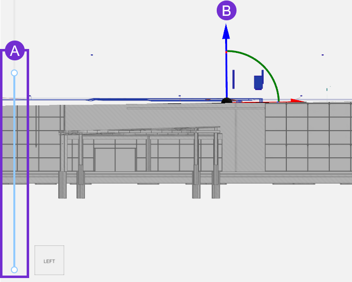 Section Slider
The  Section Slider on the left-hand side of the viewer allows you to easily cut through the model horizontally from the top or bottom using either of the two points.
section plane in the y-axis.
Bookmarks
 Bookmarks allow users to save specific views for quick access. This may be used to document issues, or compare with other solutions.
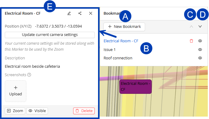
 New Bookmark - Place a new bookmark in the model.
 View bookmark - View an existing bookmark by clicking its name in the Bookmark panel.
Users can also view bookmarks by clicking their corresponding labels in the model.
The 3D Solution Viewer will zoom in to the bookmark and display the
 Bookmark information panel.
 View previous bookmark - View the previous bookmark as listed in the Bookmark panel.
 View next bookmark - View the next bookmark as listed in the Bookmark panel.
 Bookmark information panel - Shows information about the selected bookmark and contains tools for updating it.
Delete
.png) - Delete the bookmark.
- Delete the bookmark.This action can’t be undone.
In the Bookmark panel, this button appears when you hover over the bookmark.
Visibility toggle - Show
.png) or hide
or hide .png) the bookmark in the model.
the bookmark in the model. Accessible in both the Bookmark panel and
 Bookmark information panel.
If Bookmarks is configured to be hidden in View Controls, all bookmarks will be hidden from view even if this visibility toggle is turned on.
Bookmark information panel
 In the Bookmark information panel, users can do the following:
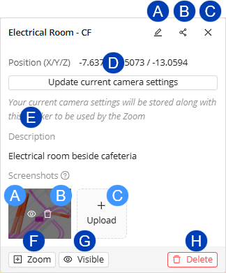
 Edit Bookmark - Edit the Name and Description of the bookmark.
 Share Bookmark - Copy a shareable URL of the bookmark.
 Close Bookmark information panel - Close the Bookmark information panel and deselect the bookmark in the Bookmark panel.
 Update current camera settings - Make the current view the default when viewing the bookmark.
 Description - Displays the description of the bookmark.
Screenshots - Images related to the bookmark which may be used to show the bookmark in different views.
 Open screenshot - Open the screenshot in the image viewer.
 Delete screenshot - Delete the screenshot.
 Upload new screenshot - Upload a new screenshot.
 Zoom - Zoom in to the position of the bookmark.
 Visibility toggle - Show or hide the bookmark.
  Delete - Delete the bookmark.
This action can’t be undone.